高压下 COH₂层流火焰速度测定与动力学模型构建

N14-高压下 COH₂层流火焰速度测定与动力学模型构建(High-pressure laminar flame speeds and kinetic modeling of carbon monoxide_hydrogen combustion)
摘要:
本文采用定压球形火焰法,测量 1–40 atm 下 CO/H₂/ 空气及 CO/H₂/O₂/ 氦气混合物的层流火焰速度。基于最新反应速率与热力学数据构建 CO-H₂氧化动力学模型,通过从头算得到 CO+HO₂→CO₂+OH 的反应速率常数。模型经对冲火焰点火温度、流动反应器组分分布、激波管点火延迟数据验证,可精准预测高压宽工况(1–40 atm、当量比 0.5–5.0)燃烧特性。结果表明,优化后的核心反应速率显著提升预测精度,优于 Li 机理与 Davis 优化机理,为高压内燃机氢 - 一氧化碳燃烧模拟提供可靠动力学基础。
Abstract
Laminar flame speeds were accurately measured for CO/H2/air and CO/H2/O2/helium mixtures at dif- ferent equivalence ratios and mixing ratios by the constant-pressure spherical flame technique for pressures up to 40 atmospheres. A kinetic mechanis m based on recently published reaction rate constants is present- ed to model these measured laminar flame speeds as well as a limited set of other experimental data. The reaction rate constant of CO + HO2 → CO2 + OH was determined to be k = 1.15 × 10⁵ T2.278 exp(_17.55 kcal/RT) cm3 mol__1 s__1 at 300–2500 K by ab initio calculations. The kinetic model accurately predicts our measured flame speeds and the non-premixed counterflow ignition temperatures determined in our previous study, as well as homogeneous system data from literature, such as concentration profiles from flow reactor and ignition delay time from shock tube experiments.
◎ 2006 The Combustion Institute. Published by Elsevier Inc. All rights reserved.
Keywords: Laminar flame speeds; Kinetics; Reaction mechanis m; CO–H2 oxidation
1. Introduction
Next to H2, the oxidation of CO–H2 mixtures is perhaps the most important building block in the hierarchy of hydrocarbon oxidation. As a result, extensive investigations based on both homogeneous chemical systems, such as the shock tube and flow reactor, and inhomogeneous diffu- sive systems, such as the laminar flame speed and the counterflow ignition/extinction states, have been performed to determine this oxidation mechanis m comprehensively. Considering the most recent literature, we note that experimental laminar flame speeds of CO/H2/air mixtures were eported by Brown et al. [1], Hassan et al. [2], McLean et al. [3], and Vagelopoulos and Egolfo- poulos [4], at pressures from atmospheric to a few atmospheres, while counterflow ignition data up to a few atmospheres were acquired by Fotache et al. [5]. Brezinsky et al. [6] recently reported a high-pressure experimental study on CO–H2 mixtures in a shock tube spanning pres- sures from 25 to 550 bars over the temperature range of 1000–1500 K. In terms of the develop- ment of the oxidation mechanis ms of CO–H2, a comprehensive mechanis m was proposed in the 1990s by Yetter et al. [7] based on an evaluation of relevant kinetic parameters and flow reactor experiments. Their mechanis m was then updated [8,9] and extended to a C1 mechanis m by Li et al. [10] to predict a wide range of flame and flow reactor experiments. Furthermore, Davis et al.
[11] developed a mechanis m based on optimiza- tion of the CO–H2 kinetic rate constants and
available combustion data, while Zsly et al. [12]
performed an uncertainty a nalysis of the CO–H2 mechanis m based on the Leeds methane oxidation mechanis m [13] with the latest reaction kinetic and thermodynamic data.
Such worthy activities have yielded mecha- nis ms that at present seem to be reasonably pre- dictive and comprehensive for the systems tested. On the other hand, new information that could affect the accuracy of some of the key reactions have been reported recently. Also, the comprehen- siveness of the existing mechanis ms has not been subjected to tests involving very-high-pressure flame propagation, which after all is one of the primary combustion modes through which hydro- carbons are consumed in internal combustion engines. These considerations have therefore led to the objectives and focuses for the present study, namely to: (1) experimentally determine the lami- nar flame speeds of various mixtures of CO and H2 at elevated pressures up to 40 atmospheres;
(2) present a CO–H2 oxidation mechanis m based on recent kinetic information and calculated reac- tion rate constant and evaluate the compiled mechanis m by comparing its predictions with those of the measured laminar flame speeds as well as experimental data for various systems as obtained from the literature.
In the following, we shall first present the experimental methodology for the flame speed determination, and then specify the aspects of the mechanis m that have been revised. The numerical result of this mechanis m are then com- pared with the present laminar flame speeds as well as the ignition temperatures, concentration profiles, and ignition delay times from the litera- ture. It is noted that due to the length limitation and the need to document the mechanis m, through Table 1, which is expected to be of utility in further studies in mechanis m adoption and development, presentation of all aspects of the work is necessarily rather brief. It will nevertheless be demonstrated in due course that the present effort has indeed led to a CO–H2 mechanis m that is of enhanced accuracy and comprehensiveness.
2. Experiment
A recently developed dual-chamber apparatus for constant, high-pressure flame studies [14] was employed to measure the laminar flame speed. The apparatus consists of a s m all inner chamber and a substantially larger outer chamber that are filled with the test mixture and inert, respectively. The two chambers are separated by an O-ring sealed sleeve with holes that are initially offset from each other but are aligned upon ignition. A run begins by spark ignition at the center of the inner chamber, generating an outwardly propagating premixed flame. The flame is quenched upon contact with the inert as it reaches the sleeve and before noticeable rise in the chamber pressure. This specific design feature allows experimentation with optical windows at very high initial pressures, up to 60 atmospheres. It also ensures that the flame propagation takes place under constant chamber pressure and upstream temperature. The time resolved schlieren flame images are recorded using a high-speed digital camera. The experiments were conducted using either nitrogen or helium as the diluent, at the lower and higher pressure ranges, respectively. The need to use helium was based on the observation [14] that the outwardly propa- gating flame becomes cellularly unstable at higher pressures, about 5 atmospheres for the present experimentation. Substituting N2 by He then increases the mixture Lewis number, thereby sup- pressing the formation of wrinkles over the flame surface. The fundamental chemistry of the phe- nomena is of course unaffected through such a substitution. The mixture composition is defined through aCO + (1 _ a)H2 + 1/φ(0.5O2 + 1.88N2) for CO/H2/air, and aCO + (1 _ a)H2 + 1/φ (0.5O2 + 3.5N2) for CO/H2/O2/He, where a is the CO fraction of the fuel mixtures, and φ is the equivalence ratio. All experiments were carried out at room temperature, 298 ± 3 K.
3. Kinetic mechanis m
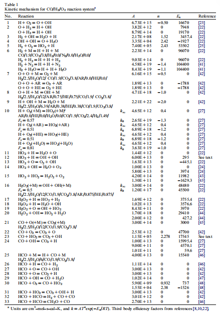
The detailed CO/H2/O2 kinetic mechanis m with elementary reaction rate constants is listed in Table 1. The thermochemical properties for the species in the mechanis m were obtained from the NIST-JANAF Thermochemical Tables [15].
The ΔH298 values for the following species were
taken from recently published data: OH of 8.91 ± 0.07 kcal/mol by Ruscic et al. [16], HO2 of 3.2 ± 0.5 kcal/mol by Ramond et al. [17], CO2 of _94.04 ± 0.03 kcal/mol by Ruscic et al.
[18], and HCO of 10.58 ± 0.10 kcal/mol by Becer- ra et al. [19]. The transport parameters were obtained from the Sandia CHEMKIN transport database. The SENKIN, PREMIX, and SHOCK codes from the CHEMKIN package [20] were used to calculate the species concentration pro- files, flame speeds, and ignition delay times. Coun- terflow ignition calculations were performed using the flame continuation method of Nishioka et al.
[21]. The calculations first determined the steady- state solutions at different hot boundary tempera- tures assuming potential flow, and the peak mole fraction of the hydrogen atom was used to moni- tor the system response. The ignition temperature was then determined as the hot boundary temper- ature at the turning point of the resulting S-curve.
Most of the reaction rate constants in the mechanis m were abstracted from the latest evalu- ation on the kinetic data for combustion modeling and recently published literature [22–25]. The
third-body efficient of helium was assumed to be the same as that of argon to simulate flame speeds where helium is the diluent. A brief description of the key rate coefficients in this mechanism is given below.
The reaction of OH with CO has been thor- oughly studied experimentally and theoretically (e.g., Ref. [26,27]), because this reaction path is responsible for the major fraction of energy release in the oxidation of hydrocarbons to CO2 and H2O, and this reaction rate is the most sensi- tive for the prediction of CO–H2 flame speed data (e.g., Ref. [3]). Although this reaction exhibits strong non-Arrhenius behavior at moderate and low temperatures, its reaction rate approaches the low-pressure limit at the temperatures above 1000 K [11,27,28]. Therefore, the low-pressure limit rate recommended by Troe [27] was adopted in our mechanism to model the experimental data considered herein.
The reaction H + O2 + M → HO2 + M pro- vides another route for the conversion of CO to CO2 through CO + HO2 → CO2 + OH at high pressures or in the initial stages of CO oxidation [29]. However, the rate constant for CO + HO2 at temperatures above 800 K is limited to indirect determinations [30–33]. Atri et al. [33] reported this reaction rate as k = 5.97 × 10¹³ exp(_22.94 kcal/RT) cm3 mol__1 s__1 based on their results from thermal reactions at 713– 773 K. Volman et al. [34] theoretically investigat- ed the reaction of CO + HO2 using ab initio CISD calculations based on unrestricted Hartee–Fock (UHF) optimized geometries. Their calculated activation energy is in agreement with that from Atri et al. [33], and as such a rate constants at 250–800 K based on the rate constant of Atri et al. [33] and the hard-sphere-collision Arrhenius modification was recommended [37]. However, the practical applications support the lower reac- tion rate above 1000 K, and a 50% reduction of the rate by Atri et al. [33] has been used in the development of reaction mechanisms [10,11,35]. To further investigate this reaction rate, we per- formed high-level ab initio calculations with Gaussian [36]. We follow the reaction mechanism as proposed by Volman [37], with the first stage in the reaction being the formation of a free radical intermediate HO2 + CO → HOOC . O which then decomposes to yield the products, and with the rate of formation of the intermediate equal to the formation of the products. The calculated acti- vation energies for the formation of the intermedi- ate are 16.82, 17.18, 17.02, 17.81, 16.73, and 16.11 kcal/mol at the G2, G2(MP2), G3, G3(MP2), CBS-QB3, and CBS-Q levels, respec- tively, which shows that different ab initio meth- ods are in good agreement. By evaluating the forward/reverse barriers and heats of reaction, we found that the G3(MP2) energies can better characterize the potential energy surface of CO + HO2. Because the calculated heat of reaction based on the G3(MP2) energies (_62.89 kcal/mol) is closer to the value derived from currently accepted ΔH98 values (_61.91 kcal/mol), and an activation energy of 17.81 kcal/mol based on the G3(MP2) calculation is closer to the experimentally obtained value (22.94 kcal/mol) [33]. By using the MP2(full)/6- 31G(d,p) optimized geometries and canonical transition state theory, we calculated this rate con- stant to be k = 1.15 × 10⁵ T2.278exp(_17.55 kcal/ RT) cm3 mol__1 s__1 at 300–2500 K, and this is the rate used in our reaction mechanism.
4. Results and comparisons
4.1. Laminar flame speeds
The measured laminar flame speeds for CO/ H2/air and CO/H2/O2/helium mixtures as a func- tion of equivalence ratio at different mixing ratios for pressures of 1, 2, 5, 10, 20, and 40 atmospheres are shown in Figs. 1 and 2, with comparisons to measured data from literature and also to calcu- lated flame speed data using different mechanisms. The measured flame speeds increase with increas- ing H2 content in the CO/H2 mixtures, while they decrease with increasing pressure for the helium-diluted mixtures. For the air-diluted mixture of CO:H2 = 95:5, our measured flame speed data are slightly lower (2–6 cm/s) than those of McLean et al. [3]. As shown in Fig. 1, our mea- sured flame speed data for the mixture of CO:H2 = 50:50 at atmospheric conditions show excellent agreement with those of Faeth et al. [2] for fuel-lean conditions; the maximum value in the curve is ca. 7 cm/s lower than that of McLean et al. [3], but they show agreement with the data of McLean et al. [3] at fuel-rich conditions.
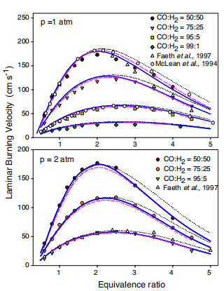
Fig. 1. Measured and calculated laminar flame speeds vs. equivalence ratio for different CO/H2/air mixtures at 1 and 2 atmospheres. Solid line, model from this work; dashed line, model from Davis et al. [11], dotted line: model from Li et al. [10].
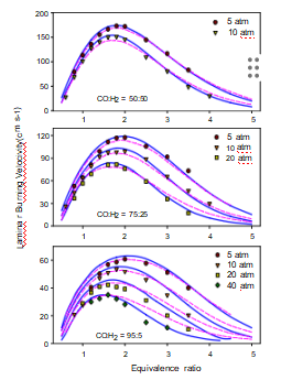
Fig. 2. Measured and calculated laminar flame speeds vs. equivalence ratio for different CO/H2/He/O2 mix- tures at 5, 10, 20, and 40 atmospheres. Solid line, model from this work; dashed line, model from Davis et al. [11].
Overall, the model predictions using our mech- anism agree very well with our experimental data at different fuel concentrations and pressures. The calculated flame speeds using the mechanism of Li et al. [9] show good agreement with the data of McLean et al. [3], but it over-predicts our mea- sured flame speed data at rich conditions. The cal- culated flame speeds from the optimized mechanism of Davis et al. [11] show close agree- ment with our experimental results at pressures of 1–5 atmospheres, but the discrepancy increases at fuel-rich condition when the chamber pressure is above 5 atmospheres. Our model predictions show much better agreement than those from the optimized model at higher pressures even though a discrepancy of 4–5 cm/s still exists.
However, for these fast flames, such a discrepancy is within the error range of the experiment. Because we used ultra high purity grade fuels and certified oxygen/nitrogen in our experiments, and had a very good vacuum procedure, trace amount of water, if any, should be in the ppm range. Such small amount of water should have negligible effect on the flame speeds, especially giv- en that the CO used already has hydrogen added as an ‘‘impurity’’ as compared to pure CO, which would be very sensitive to even trace amount of water. The satisfactory performance of our model is ascribed to the accurate elementary rate con- stants for the nature of fundamental reaction mechanism. As the laminar flame propagation rate is determined by chemical reaction rates and heat release, which are coupled with heat conduc- tion and molecular diffusion, this discrepancy could be the results of both kinetic and transport uncertainties.
4.2. Counterflow ignition temperatures
Ignition temperatures provide good target points for the testing of kinetic mechanisms in the moderate temperature regime. Figure 3 com- pares the calculated counterflow ignition tempera- tures from different models with our previous experimental data at atmospheric pressure [5]. Our model prediction is very close to that of Davis et al. [11] at lower H2 concentrations, and close to that of Li et al. [10] at higher H2 concentrations. Overall, the prediction of our model shows much closer agreement with the experimental data than other models. Figure 4 compares the calculated ignition temperatures as a function of pressure with the experimental data at strain rates of 100 s__1 for 5% H2 in CO [5]. The calculated igni- tion temperatures show very good agreement with the experimental data [5] over the entire experi- mental pressure range, while the predictions from
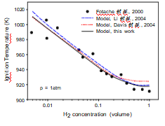
Fig. 3. Comparison of calculated ignition temperatures vs. H2 concentration with the experimental data at atmospheric conditions with the strain rate of 100 s .
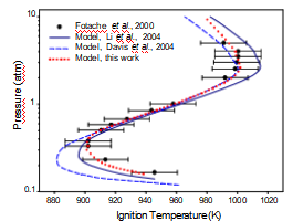
Fig. 4. Comparison of calculated ignition temperatures vs. pressure with the experimental data at the strain rate of 100 s__1 for 5% H2 in CO.
the other mechanisms [8,11] are either within or beyond the experimental error limit (±15 K) at both lower and higher pressures. A sensitivity an alysis indicated that the reactions of H + O2 = O + OH, O + H2 = H + OH, H + HO2 = OH + OH, H2 + O2 = HO2 + H, and CO + OH = CO2 + H are the most important for the prediction of ignition temperatures around 900 K at pressures lower than 0.3 atmospheres. Our satisfactory predictions strongly support the accuracy of the rate constants used in the current model.
4.3. Flow reactor and shock tube data
Adiabatic flow reactor and shock tube experi- ments provide well-characterized environments that minimize mixing and diffusion effects, and are therefore very well suited for detailed chemical kinetic modeling. Because the modeling uncertain- ties in flow reactor are relatively large, it is com- mon to shift the simulated values along the time axis to match the 50% fuel consumption [9,12,38]. Dryer et al. [35,38,39] recently per- formed several H2/O2 and CO/H2 studies utilizing these configurations. They indicated that the reac- tion of H + HO2 → OH + OH is a dominant reaction pathway in their flow reactor and kinetic modeling study of H2–O2 reaction [38]. However, there are a few rate data in the higher temperature range and the scatter is large. They estimated this rate constant as k = 7.08 × 10¹³ exp(_0.3 kcal/ RT) cm3 mol__1 s__1 to model the H2, O2, and H2O reaction profiles in their flow reactor experiment. Our mechanism supports a slightly lower rate for this reaction: k = 6.0 × 10¹³ exp(_0.3 kcal/RT) cm3 mol__1 s__1. After incorpo- rating this modified rate constant and the afore- mentioned time shifting technique, our mechanism predictions yields very close agree- ment with the experimental reaction profiles for both H2/O2/N2 and CO/H2O/O2/N2 mixtures at atmospheric pressure, as shown in Figs. 5 and 6. Furthermore, because this reaction is also domi- nant in modeling the global combustion parame- ters of flame speed and ignition temperature, the good agreements between our model and our combustion experiments provides further support for the accuracy of this modified reaction rate.
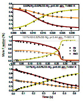
Fig. 5. Comparison of calculated and experimental reaction profiles of H2/O2/N2 mixtures in an atmospher- ic pressure flow reactor. Symbol, Muller et al. [8].
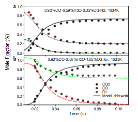
Fig. 6. Comparison of calculated and experimental reaction profiles of CO/H2O/O2/N2 mixtures in an atmospheric pressure flow reactor. Symbol, Yetter et al. [39]. (a) Model prediction was time shifted by 0.003 s. (b) Model prediction was time shifted by 0.04 s.
As indicated above, the reaction of CO + HO2 is another important route for CO consumption at higher pressures, and as such, our model predicts the CO consumption rate well at elevated pres- sures of 1, 2.4, and 9.6 atmospheres [8] even with- out a time shift. When using the rate from Mueller et al. [8] in our model, the predicted CO concen- tration at 9.6 atmospheres shows a larger discrep- ancy with the experimental data at longer reaction times as shown by the dashed line in Supplemental material (Fig. S1). The good agreement between the experiment and our model supports the accu- racy of the CO + HO2 rate constant based on our theoretical calculations. Our model also shows satisfactory agreement for the shock tube ignition time delays [40], as shown in Fig. S2.
5. Concluding remarks
Experimental laminar flame speeds were accu- rately measured for CO/H2/air and CO/H2/O2/ He mixtures at different equivalence ratios and mixing ratios up to 40 atmospheres using the con- stant-pressure spherical flame technique. The reaction rate constant of CO + HO2 → CO2 + OH was calculated based on ab initio theo- ry and canonical transition state theory. A kinetic mechanism based on recently published and calcu- lated rate constants is presented to model the mea- sured laminar flame speeds as well as the experimental data from counterflow ignition, flow reactor, and shock tube experiments in the litera- ture. The comparison between the modeling results and the laboratory measurements suggests that the accuracy of the thermochemical data and the elementary rate constants is crucial for a satis- factory performance of the reaction mechanism.
Acknowledgments
This work was supported by the Air Force Of- fice of Scientific Research and the Army Research Office, under the technical monitoring of Drs. Ju- lian Tishkoff and Kevin McNes by, respectively.
Appendix A. Supplementary data
Supplementary data associated with this article can be found in the online version at doi:10.1016/ j.proci.2006.07.193.
References
[1] M.J. Brown, I.C. Mclean, D.B. Smith, et al., Proc. Combust. Inst. 26 (1996) 875–881.
[2] M.I. Hassan, K.T. Aung, G.M. Faeth, J. Prop. Power 13 (2) (1997) 239–245.
[3] I.C. McLean, D.B. Smith, S.C. Taylor, Proc. Combust. Inst. 25 (1994) 749–757.
[4] C.M. Vagelopoulos, F.N. Egolfopoulos, Proc. Combust. Inst. 25 (1994) 1317–1323.
[5] C.G. Fotache, Y. Tan, C.J. Sung, et al., Combust. Flame 120 (2000) 417–426.
[6] R. Sivaramakrishnan, A. Comandini, R.S. Tranter, et al., in: Proceedings of 6th International Conference on Chemical Kinetics, NIST, Gaithers burg, MD, 2005, Poster L14.
[7] R.A. Yetter, F.L. Dryer, H. Rabitz, Combust. Sci. Technol. 79 (1–3) (1991) 97–128.
[8] M.A. Mueller, R.A. Yetter, F.L. Dryer, Int. J. Chem. Kinet. 31 (10) (1999) 705–724.
[9] J. Li, Z. Zhao, A. Kazakov, et al., Int. J. Chem. Kinet. 36 (10) (2004) 566–575.
[10] J. Li, Z. Zhao, A. Kazakov, et al., 30th International Symposium on Combustion, University of Illinois, Chicago, Illinois, 2004, Poster 1F1-04.
[11] S.G. Davis, A.V. Joshi, H. Wang, et al., Proc. Combust. Inst. 30 (2005) 1283–1292.
[12] I.G. Zsly, J. Zdor, T. Turnyi, Proc. Combust. Inst. 30 (2005) 1273–1281.
[13] K.J. Hughes, T. Turnyi, A.R. Clague, et al., Int. J. Chem. Kinet. 33 (9) (2001) 513–538.
[14] S.D. Tse, D.L. Zhu, C.K. Law, Proc. Combust. Inst. 28 (2000) 1793–1800.
[15] M.W. Chase Jr., J. Phys. Chem. Ref. Data 4th Ed. (Monograph 9), 1998, pp. 1–1951.
[16] B. Ruscic, A.F. Wagner, L.B. Harding, et al., J. Phys. Chem. A 106(11) (2002), 2727–2747.
[17] T.M. Ramond, S.J. Blanks by, S. Kato, et al., J. Phys. Chem. A. 106 (42) (2002) 9641–9647.
[18] B. Ruscic, R.E. Pinzon, M.L. Morton, et al., J. Phys. Chem. A. 108 (45) (2004) 9979–9997.
[19] R. Becerra, I.W. Carpenter, R. Walsh, J. Phys. Chem. A 101 (23) (1997) 4185–4190.
[20] R.J. Kee, F.M. Rupley, J.A. Miller, CHEMKIN II, 4.5 ed., Sandia National Laboratories, Combustion Research Facility, Livermore, CA, 1995.
[21] M. Nishioka, C.K. Law, T. Takeno, Combust. Flame 104 (3) (1996) 328–342.
[22] D.L. Baulch, C.T. Bowman, C.J. Cobos, et al., J. Phys. Chem. Ref. Data 34 (3) (2005) 757–1555.
[23] S.M. Hwang, S.-O. Ryu, K.J.D. Witt, et al., Chem. Phys. Lett. 408 (1–3) (2005) 107–111.
[24] C. Kappel, K. Luthe, J. Troe, Phys. Chem. Chem. Phys. 4 (2002) 4392–4398.
[25] J.C. Michael, J.W. Sutherland, L.B. Harding, et al., Proc. Combust. Inst. 28 (2000) 1471–1478.
[26] M.S. Wooldridge, R.K. Hanson, C.T. Bowman, Proc. Combust. Inst. 25 (1994) 741–748.
[27] J.R. Troe, Proc. Combust. Inst. 27 (1998) 167–175.
[28] D. Fulle, H.F. Hamann, H. Hippler, et al., J. Chem. Phys. 105 (3) (1996) 983–1000.
[29] I. Glassman, Combustion, Academic, San Diego, CA, 1996.
[30] J. Vandooren, L. Oldenhove de Guertechin, P.J. van Tiggelen, Combust. Flame 64 (1986) 127–139.
[31] I.A. Vardanyan, G.A. Sachyan, A.B. Nalbandyan, Int. J. Chem. Kinet. 7 (1975) 23.
[32] M.B. Colket III, D.W. Naegeli, I. Glassman, Proc. Combust. Inst. 16 (1977) 1023.
[33] G.M. Atri, R.R. Baldwin, D. Jackson, et al., Combust. Flame 30 (1977) 1–12.
[34] T.L. Allen, W.H. Fink, D.H. Volman, J. Phys. Chem. 100 (13) (1996) 5299–5302.
[35] M.A. Mueller, R.A. Yetter, F.L. Dryer, Int. J. Chem. Kinet. 32 (6) (2000) 317–339.
[36] M.J. Frisch et al., Gaussian 03, Gaussian Inc., Pitts burgh PA, 2003.
[37] D.H. Volman, J. Photochchem. Photobiol. A: Chem. 100 (1–3) (1996) 1–3.
[38] M.A. Mueller, T.J. Kim, R.A. Yetter, et al., Int. J. Chem. Kinet. 31 (2) (1999) 113–125.
[39] R.A. Yetter, F.L. Dryer, H. Rabitz, Combust. Sci. Technol. 79 (1-3) (1991) 129–140.
[40] A.M. Dean, D.C. Steiner, E.E. Wang, Combust. Flame 32 (1978) 73–83.
[41] N. Cohen, K.R. Westberg, J. Phys. Chem. Ref. Data 12 (3) (1983) 531–590.
[42] W. Tsang, R.F. Hampson, J. Phys. Chem. Ref. Data 15 (1986) 1087–1279.
[43] H. Hippler, J. Troe, J. Willner, J. Chem. Phys. 93 (3) (1990) 1755–1760.
[44] H. Hippler, H. Neunaber, J. Troe, J. Chem. Phys. 103 (9) (1995) 3510–3516.
[45] R.R. Baldwin, D. Jackson, A. Melvin, et al., Int. J. Chem. Kinet. 4 (1972) 277.
[46] G. Friedrichs, J.T. Herbon, D.F. Davidson, et al., Phys. Chem. Chem. Phys. 4 (23) (2002) 5778–5788.
[47] D.L. Baulch, C.J. Cobos, R.A. Cox, et al., J. Phys. Chem. Ref. Data 21 (3) (1992) 411–429.
[48] C.-C. Hsu, A.M. Mebel, M.C. Lin, J. Chem. Phys. 105 (6) (1996) 2346–2352.
Comments
John Griffiths, University of Leeds, UK. It is very interesting to see your revision of the rate parameters for the reaction HO2 + CO. This agrees with our under- standing that the reaction should be slower than is pre- dicted by the parameters from Mueller et al. The values you give would put the distribution of the predicted igni- tion delay in Fig. 4 of our preceding paper (Mittal et al.) at a position corresponding to logA = _10.9, which is
close to our expectations.
Steve Klippenstein kindly did some transition state theory calculations for us after our paper was accepted, which also lead to a lower rate constant. He gave two functions, one based on a single activation barrier and another based on a double activation barrier.
The data are as follows.
TST1: k = 2.703 × 10__20 . T2.482 . exp(__8472/T) cm3 molecule__1 s__1
TST2: k = 1.149 × 10__17 . T1.609 . exp(__8805/T) cm3 molecule__1 s__1
Reply. We are pleased to see that your experimental observation supports our theoretical rate constant for the CO + HO2 reaction. We have, in addition, found that the first function of the CO + HO2 rate constant by Klip- penstein is only a factor of0.8lower than our recommend- ed rate constant within the temperature range of 800– 2500 K. Furthermore, our QRRK-master equation an al- ysis indicated that the forward rate constant to products based on our double activation barriers as presented at the meeting is also consistent with Klippenstein’s second function of the CO + HO2 rate constant.
●
Anthony Dean, Colorado School of Mines, USA. For your calculated value of k for CO + HO2 = CO2 + OH, why was it necessary to assume that the product forma- tion was the same as the rate of formation of the inter- mediate complex?
Reply. This is a very good question. This rate constant based on double activation barriers is about a
factor of 1.1–1.7 (T = 300–2500 K) lower than that based on a single activation barrier, since the second barrier is only few kcal/mol, so our calculated k using the assumption presents this rate constant very reason- ably, and it does not contain errors introduced from the uncertainties of parameters used in QRRK-master equation an alysis.
●
John Simmie, National University of Ireland, Ireland. You are to be congratulated for comparing your exper- iments against three mechanisms and not just your own. But what are the essential differences between them that make yours better—is it the chemistry and/or the trans- port properties?
Reply. Since the comparison was conducted for dif- ferent reaction mechanisms, but basically the same transport properties, it is reasonable to infer that it is the revised rates that affected the difference.
●
Ken Brezinsky, University of Illinois at Chicago, USA. I was surprised to see that you were using Dean’s shock tube ignition delay data from 1978 (in paper). Is there no other shock tube ignition delay data for you to model?
Reply. We used Dean’s shock tube data because it is a widely cited source. The most recent shock tube data are those by Petersen et al. [1]. We have now compared our calculated values against their data for 5 sets of fuel-lean (φ = 0.5) CO/H2/air mixtures for 890 K < T < 1285 K and pressure near 1 atm, and found fairly good agreement.
Reference
[1] D. Kalitan, E. Petersen, AIAA-2005-3767, 41st AIAA/ASME/SAE/ASEE Joint Propulsion Confer- ence and Exhibit, Tucson, Arizona, 2005.
免责声明:
本页面/内容部分素材来源于互联网公 开 信 息,旨在传递更多信息,不代表本平台立场。
版权归原作者或机构所有,如涉及侵权,请通过平台联系我们,我们将在核实后第一时间处理。
本平台对转载内容的真实性、准确性不作任何保证,用户需自行判断并承担使用风险。