DEFORM-3D technical product specifications(产品说明)

摘要:
本文为 DEFORM-3D 产品技术说明,该软件基于有限元法,专注于三维金属成形过程仿真,可模拟锻造、切削、轧制、挤压等多种冷热成形工艺。软件支持大变形材料流动、热力耦合分析,搭载全自动网格重划分功能,兼容 STL 等主流 CAD 格式,边界条件可自动生成。内置多类材料模型,具备模具应力、过盈配合、一步模具分析等功能,后处理包含流线、点追踪、云图等模块,支持 OpenGL 图形显示。软件适配 Windows 与 UNIX 系统,支持多 CPU 并行,配备超 150 种材料数据库,同时提供培训、技术支持与版本更新服务。
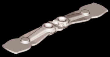
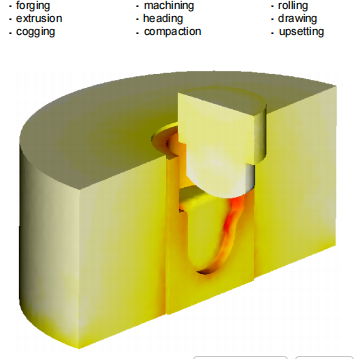
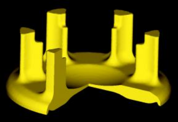
DEFORM TM -3D is applicable to a wide range of processes and geometries including a hot forged steering link (above) and cold formed gear carrier (below). On the right, a stress ana lysis is shown of a die assembly, including interference fit between the case and die insert. Red indicates a higher level of effective stress.
DEFORM™ -3D is a powerful process simulation system designed to an alyze the three-dimensional (3D) flow of complex metal forming processes. DEFORM™ -3D is a practical and efficient tool to predict the material flow in industrial forming operations without the cost and delay of shop trials. Typical applications include:
Based on the finite element method, DEFORM™ has proven to be accurate and robust in industrial application for more than two decades. The simulation engine is capable of predicting large deformation material flow and thermal behavior with astonishing precision.
The automatic mesh generator (AMG) produces an optimized mesh system with local element size control based on the specific process being a nalyzed. This facilitates the enhanced resolution of part features while maintaining good control of the overall problem size and computing requirements.
While DEFORM™ -3D provides sophisticated a nalysis capabilities, the graphical user interface is intuitive and easy to learn. Moreover, it provides utilities to manipulate 3D geometry, including boolean capabilities to trim flash. DEFORM™ -3D is the foundation for a comprehensive modeling system that integrates raw material production, forming, heat treatment and machining.
DEFORM™ -3D continues the tradition of accuracy and state-of-the-art capabilities established in the early 1980’s. Scientific Forming Technologies Corporation has the experience and background to provide unparalleled training and technical support.
Technical Product Specifications
• DEFORM™ -3D simulates material flow, die fill, forming load, tool stress and defect formation in cold, warm and hot forming processes.
• Fully automatic optimized remeshing is performed during a simulation with the AMG mesh generator. No user interven- tion is required.
• DEFORM™ -3D supports input from CAD systems in the form of a surface or solid mesh, as well as the stereolithographics (STL/SLA) format.
• Boundary condition generation during preprocessing has been automated to ensure fast and reliable data preparation.
• Forming equipment interaction during the deformation pro- cess is an alyzed for hydraulic presses, hammers, screw presses, mechanical presses, rolling mills and rotary forges.
• Material models include elastic, rigid plastic, thermal elasto- plastic, thermal rigid-viscoplastic, porous and rigid.
• Heat transfer between and within objects can be an alyzed as a stand-alone process or as an integral part of a deformation simulation.
• A very efficient one-step die stress an alysis is available, which includes multiple deforming body an alysis and interference-fit between dies.
• FLOWNET and point tracking are included in the powerful postprocessor along with deformation, contour plots, load- stroke prediction and more.
• The postprocessor supports OpenGL graphics. This provides the user with capabilities to examine and understand the solution results graphically. Transparency and slicing allows user to ‘see’ inside of the work piece or die.
• Mirroring capabilities in the postprocessor provide the user with an opportunity to simulate a symmetrical section of the process for computational efficiency while retaining the ability to display the entire geometry.
Computer System Requirements
• DEFORMTM- 3D runs on popular UNIX workstations and WINDOWS NT/2000/XP.
• The minimum recommended configuration is 512 MB RAM. 1+ GB RAM may be required for large models.
• Multiple CPU support is available with the MPI option.
• At least 5 GB of free disk space, a color monitor and a POSTSCRIPT printer are recommended. A WINDOWS printer is recommended for NT/2000XP systems.
• DEFORMTM- 3D is distributed on CD -ROM or via Internet download. Access to a CD writer or tape drive is recommended for back-up purposes.
• Internet access is desirable to take advantage of on-line technical support and service pack updates.
General Information
• Training, support and regular updates are available to DEFORMTM Users.
• DEFORMTM Users Group meetings are held regularly.
• The DEFORMTM Material Database with in excess of 150 materials is supplied by SFTC.
免责声明:
本页面/内容部分素材来源于互联网公 开 信 息,旨在传递更多信息,不代表本平台立场。
版权归原作者或机构所有,如涉及侵权,请通过平台联系我们,我们将在核实后第一时间处理。
本平台对转载内容的真实性、准确性不作任何保证,用户需自行判断并承担使用风险。
PDF版见附件