Particleworks 7.0.0 软件用户手册核心操作指南(UserManual)

Particleworks 7.0.0 软件用户手册核心操作指南(UserManual)
摘要:
本文系统介绍 Particleworks 7.0.0 官方用户手册核心内容,覆盖软件全流程操作规范。手册包含项目与场景管理、几何建模、输入对象设置、物理属性定义、动画控制、仿真参数配置、求解运行、结果后处理与可视化等完整模块。支持 MPS 无网格粒子法、DEM 离散元法、FVM 有限体积法与气液固多相耦合,可模拟牛顿 / 非牛顿流体、传热、曝气、刚体运动等工况。详细说明 GUI 操作、命令行运行、GPU/MPI 并行计算及数据输出格式,为工业流体仿真提供标准化操作指南与参数设置依据。
User Manual
Release 7.0.0
Prometech Software, Inc.
Jun 01, 2020
CHAPTER 1 Introduction
This document is a reference guide to using Particleworks/Granuleworks.
1.1 See Also
•Particleworks Tutorials : Consists of several samples, each of which covers essential topics such as basic simulation settings, preprocessing, and postprocessing.
•Granuleworks Tutorials : Consists of several samples, each of which covers essential topics such as basic simulation settings, preprocessing, and postprocessing.
•Particleworks Theory Manual : Describes physical models used in Particleworks. Refer to Theory Manual for details of simulation parameters.
•Granuleworks Theory Manual : Describes physical models used in Granuleworks. Refer to Theory Manual for details of simulation parameters.
•Installation Guide : Covers installation-related topics as well as system requirements.
•Release Notes : Contains record of changes made to Particleworks, such as bug fixes and new features.
1.2 Copyright Notice
All rights reserved. No parts of this work may be reproduced in any form or by any means without the written permission of Prometech Software, Inc. Products that are referred to in this document may be either trademarks and/or registered trademarks of the respective owners.
CHAPTER 2 Basics
This chapter describes the basic operations required to perform simulations.
2.1 Workflow
The basic workflow to perform a simulation is the following:
1.Create a scene (see Scenes), then create Input Objects such as geometry and inflows.
2.Create physical properties such as fluid and powder, and assign them to input objects.
3.If necessary, create Animation for input objects.
4.Configure Simulation Options such as unit system and particle size.
5.Run Simulation (and Preprocessing).
6.View generated result objects.
7.Run Postprocessing functions such as Surface Generator and Probe. Chapters following Basics explains functions used in each step of the workflow.
2.2 Projects
You start working by creating a project or by opening an existing one. A project contains one or more Scenes that manage all parameter settings and data for simulation, as well as geometry data (including file references) used in each scene.
Creating multiple Scenes under one project helps you to keep track of related simulation settings and results.
Each project has a Models Folder, which manages geometry data (including file references) used in its
scenes. This minimizes memory requirements for storage and graphics when multiple scenes use geometry data.
2.2.1 Creating Projects
1.Click the New Project button to open the New Project window.
2.Type a name for the project and specify where the project is saved.
3.Click OK to close the window. The default scene of the project opens automatically.
Note: By default, a scene is created within the project.
2.2.2 Opening projects
1.Click the Open Projects button to open the Select Projects window.
2.Select the project folder and then click Choose.
3.The project appears in the Projects window.
2.2.3 Closing Projects
1.In the Projects window, right-click the target projects.
2.In the Project Menu, click Close project.
2.2.4 Duplicating Projects
1.In the Projects window, right-click the target projects.
2.In the Project Menu, click Copy project.
2.2.5 Deleting Projects
1.In the Projects window, right-click the target projects.
2.In the Project Menu, click Delete project.
2.2.6 Project Menu
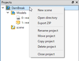
In the Projects window, right-click a project to open the popup menu. Available actions are the following:
•New Scene : Creates a new scene.
•Open directory : Opens the project folder. See Project Folder Structure for details.
•Export ZIP : Exports the contents of the project to a zipped file. See Exporting Projects for details.
•Rename project : Renames the project.
•Move project : Changes the location of the project folder.
•Copy project : Duplicates the project.
•Delete project : Deletes the project.
•Close project : Closes the project.
2.2.7 Models Folder
Geometry Files
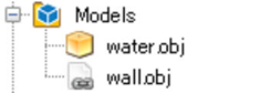
In the Projects window, the Models folder displays geometry files used in the project. There are two types of nodes for geometry files:
• External : A reference to a file that exists outside the project folder.
• Internal : An imported file that exists in the project folder.
By importing external files, the project can load the geometry entries when moved to other locations.
Note: Each geometry file is named “ID : FileName” here for the distinction between files with the same name in different folders.
Adding Geometry Files
When a geometry object is added to a scene, the enclosing project will automatically add a node (reference) to the Models folder. If the file is used in multiple scenes, no duplicates are generated in the folder.
Note: When geometry objects are removed from a scene, the corresponding files remain in the Models folder. Drag and drop the file nodes onto the scene if you want to add them to the scene again.
Geometry Information
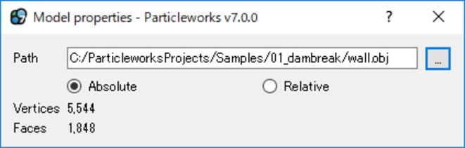
Double-click a geometry file to show the information dialog of the model.
External :
Internal  :
:
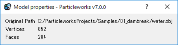
•Path : The path to the geometry file. The path is relative to the models folder when it’s not an
absolute path.
•Absolute/Relative : Switches the path of the geometry file to either absolute or relative. This action is enabled only for External files.
•Original Path : Enabled only for Internal files. The path of the original geometry file before import-
ing.
•Vertex Count : The number of vertices the geometry contains.
•Face Count : The number of faces.
2.2.8 Project Folder Structure
A set of files and folders is created under the project’s main folder. A typical project folder looks as follows:
•models : Contains geometry files (including file references).
•pwproject : Contains temporary files and miscellaneous runtime data.
•scene : Corresponds to each scene under the project.
–df : Contains DF data.
–flow_rate : Contains flow rate data (postprocessing).
–grid : Contains grid data (postprocessing).
–mapping : Contains mapping data (postprocessing).
–pathline : Contains pathline data (postprocessing).
–pre : Contains data and setting files related to preprocessing.
–probe : Contains probe data (postprocessing).
–result : Contains all particles and related simulation data.
–surface : Contains surface data (postprocessing).
–sub.json : Contains all parameters of the scene.
–tmp : Contains temporary data used for Video Output etc.
•project.properties : Contains general properties of the project.
2.2.9 Exporting Projects
You can export projects to zipped files and open them in another computer. Do the following to export a
project:
1.In the Project Menu, click Export ZIP.
2.Select the data that you want to export.
•Simulation results and postprocessing data are not recommended for exporting, as they can be too large to transfer.
•Clear the checkboxes of geometry files (models) when they contain confidential information.
•Make sure to select the log checkbox when you send your project to the support team.
更多内容见附件
免责声明:
本页面/内容部分素材来源于互联网公 开 信 息,旨在传递更多信息,不代表本平台立场。
版权归原作者或机构所有,如涉及侵权,请通过平台联系我们,我们将在核实后第一时间处理。
本平台对转载内容的真实性、准确性不作任何保证,用户需自行判断并承担使用风险。