大家一起学标准之IEC61400-1(17)

点击听全文,今天大家继续一起学IEC61400-1。
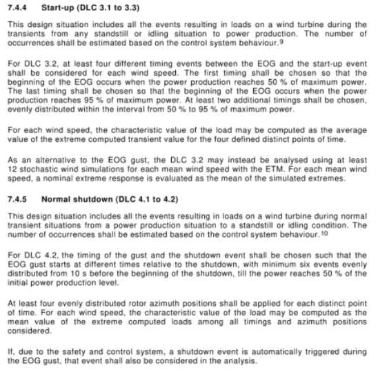
7.4.4 Start-up (DLC 3.1 to 3.3)
This design situation includes all the events resulting in loads on a wind turbine during the transients from any standstill or idling situation to power production. The number of occurrences shall be estimated based on the control system behaviour.
For DLC 3.2, at least four different timing events between the EOG and the start-up event shall be considered for each wind speed. The first timing shall be chosen so that the beginning of the EOG occurs when the power production reaches 50 % of maximum power. The last timing shall be chosen so that the beginning of the EOG occurs when the power production reaches 95 % of maximum power. At least two additional timings shall be chosen, evenly distributed within the interval from 50 % to 95 % of maximum power.
For each wind speed, the characteristic value of the load may be computed as the average value of the extreme computed transient value for the four defined distinct points of time.
As an alternative to the EOG gust, the DLC 3.2 may instead be an alysed using at least 12 stochastic wind simulations for each mean wind speed with the ETM. For each mean wind speed, a nominal extreme response is evaluated as the mean of the simulated extremes.
7.4.5 Normal shutdown (DLC 4.1 to 4.2)
This design situation includes all the events resulting in loads on a wind turbine during transient situations from a power production situation to a standstill or idling condition. The number of occurrences shall be estimated based on the control system behaviour.
For DLC 4.2, the timing of the gust and the shutdown event shall be chosen such that the EOG gust starts at different times relative to the shutdown, with minimum six events evenly distributed from 10 s before the beginning of the shutdown, till the power reaches 50 % of the initial power production level.
At least four evenly distributed rotor azimuth positions shall be applied for each distinct point of time. For each wind speed, the characteristic value of the load may be computed as the mean value of the extreme computed loads among all timings and azimuth positions considered.
If, due to the safety and control system, a shutdown event is automatically triggered during the EOG gust, that event shall also be considered in the an alysis.
As an alternative to the EOG gust, the DLC 4.2 may instead be an alysed using at least 12 stochastic wind simulations for each mean wind speed with the ETM. For each mean wind speed, a nominal extreme response is evaluated as the mean of simulated extremes.
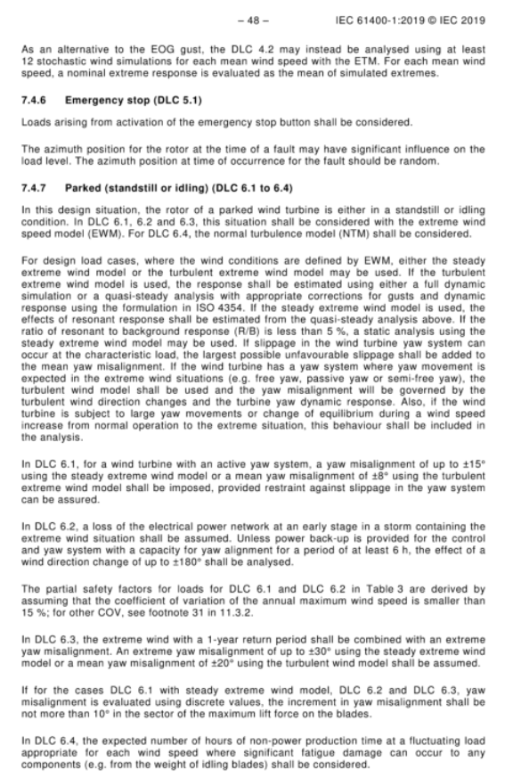
7.4.6 Emergency stop (DLC 5.1)
Loads arising from activation of the emergency stop button shall be considered.
The azimuth position for the rotor at the time of a fault may have significant influence on the load level. The azimuth position at time of occurrence for the fault should be random.
7.4.7 Parked (standstill or idling) (DLC 6.1 to 6.4)
In this design situation, the rotor of a parked wind turbine is either in a standstill or idling condition. In DLC 6.1, 6.2 and 6.3, this situation shall be considered with the extreme wind speed model (EWM). For DLC 6.4, the normal turbulence model (NTM) shall be considered.
For design load cases, where the wind conditions are defined by EWM, either the steady extreme wind model or the turbulent extreme wind model may be used. If the turbulent extreme wind model is used, the response shall be estimated using either a full dynamic simulation or a quasi-steady an alysis with appropriate corrections for gusts and dynamic response using the formulation in ISO 4354. If the steady extreme wind model is used, the effects of resonant response shall be estimated from the quasi-steady an alysis above. If the ratio of resonant to background response (R/B) is less than 5 %, a static an alysis using the steady extreme wind model may be used. If slippage in the wind turbine yaw system can occur at the characteristic wind load, the largest possible unfavourable slippage shall be added to the mean yaw misalignment. If the wind turbine has a yaw system where yaw movement is expected in the extreme wind situations (e.g. free yaw, passive yaw or semi-free yaw), the turbulent wind model shall be used and the yaw misalignment will be governed by the turbulent wind direction changes and the turbine yaw dynamic response. Also, if the wind turbine is subject to large yaw movements or change of equilibrium during a wind speed increase from normal operation to the extreme situation, this behaviour shall be included in the an alysis.
In DLC 6.1, for a wind turbine with an active yaw system, a yaw misalignment of up to ±15° using the steady extreme wind model or a mean yaw misalignment of ±8° using the turbulent extreme wind model shall be imposed, provided restraint against slippage in the yaw system can be assured.
In DLC 6.2, a loss of the electrical power network at an early stage in a storm containing the extreme wind situation shall be assumed. Unless power back-up is provided for the control and yaw system with a capacity for yaw alignment for a period of at least 6 h, the effect of a wind direction change of up to ±180° shall be an alysed.
The partial safety factors for loads for DLC 6.1 and DLC 6.2 in Table 3 are derived by assuming that the coefficient of variation of the annual maximum wind speed is smaller than 15 %; for other COV, see footnote 31 in 11.3.2.
In DLC 6.3, the extreme wind with a 1-year return period shall be combined with an extreme yaw misalignment. An extreme yaw misalignment of up to ±30° using the steady extreme wind model or a mean yaw misalignment of ±20° using the turbulent wind model shall be assumed.
If for the cases DLC 6.1 with steady extreme wind model, DLC 6.2 and DLC 6.3, yaw misalignment is evaluated using discrete values, the increment in yaw misalignment shall be not more than 10° in the sector of the maximum lift force on the blades.
In DLC 6.4, the expected number of hours of non-power production time at a fluctuating load appropriate for each wind speed where significant fatigue damage can occur to any components (e.g. from the weight of idling blades) shall be considered.
7.4.4 启动工况(DLC 3.1~3.3)
本设计工况包含机组从静止或空转状态过渡至发电状态的瞬态过程中,所有会使风力发电机组承受荷载的事件。事件发生次数应根据控制系统特性进行估算。
对于 DLC 3.2,每种风速下,至少应考虑极端运行阵风(EOG)与启动事件之间 4 组不同时序工况。第 1 组时序选取为:极端运行阵风起始时刻对应机组出力达到最大功率的 50%;最后一组时序选取为:极端运行阵风起始时刻对应机组出力达到最大功率的 95%。另外至少选取两组时序,均匀分布在最大功率 50%~95% 区间内。
对于每种风速,荷载特征值可取上述 4 个不同时刻瞬态极限计算值的平均值。
作为采用极端运行阵风(EOG)方案的替代方法,DLC 3.2 也可采用极端湍流模型(ETM),对每个平均风速开展至少 12 次随机风仿真。对于每一平均风速,标称极限响应取各次仿真极限响应的平均值。
7.4.5 正常停机(DLC 4.1~4.2)
本设计工况包含机组从发电状态过渡至静止或空转状态的瞬态过程中,所有会使风力发电机组承受荷载的事件。事件发生次数应根据控制系统特性进行估算。
对于 DLC 4.2,应当合理选取阵风与停机事件的时序,使得极端运行阵风(EOG)相对停机起始时刻在不同时间点启动;至少设置 6 组工况,时间均匀分布于停机前 10 秒至出力降至初始发电功率 50% 的区间内。
每个时序工况下至少采用 4 个均匀分布的风轮方位角。对于每种风速,荷载特征值可取所有时序、所有方位角对应的极限计算荷载的平均值。
若安全与控制系统会在极端运行阵风持续期间自动触发停机,则该事件也应当纳入分析。
作为采用极端运行阵风(EOG)方案的替代方法,DLC 4.2 也可采用极端湍流模型(ETM),对每个平均风速开展至少 12 次随机风仿真。对于每一平均风速,标称极限响应取各次仿真极限响应的平均值。
7.4.6 紧急停机(DLC 5.1)
应当考虑按下紧急停机按钮产生的各类荷载。
故障发生瞬间风轮所处方位角可能对荷载大小产生显著影响。故障发生时刻对应的风轮方位角宜随机选取。
7.4.7 停机静置工况(静止或空转)(DLC 6.1~6.4)
本设计工况下,停机静置机组的风轮处于静止或空转状态。DLC 6.1、6.2、6.3 工况应采用极端风速模型(EWM);DLC 6.4 工况应采用正常湍流模型(NTM)。
对于采用极端风速模型(EWM)定义风况的设计荷载工况,可选用稳态极端风模型或者湍流极端风模型。若采用湍流极端风模型,可采用完整动态仿真,或者依据 ISO 4354 公式开展准稳态分析,并对阵风效应与动态响应进行合理修正。若采用稳态极端风模型,共振响应影响可通过上述准稳态分析进行评估。若共振响应与背景响应比值(R/B)小于 5%,可采用稳态极端风模型开展静力分析。若特征风荷载作用下偏航系统会发生滑移,则应在平均偏航偏差基础上叠加最不利滑移量。若机组偏航系统在极端风况下允许发生偏航运动(例如自由偏航、被动偏航、半自由偏航),则必须采用湍流风模型,偏航偏差由湍流风向变化和机组偏航动态响应共同决定。此外,若风速从正常运行值升高至极端工况过程中,机组会出现大幅偏航运动或者平衡点偏移,则该特性应当纳入分析。
对于配备主动偏航系统的机组,在 DLC 6.1 工况下:若采用稳态极端风模型,偏航偏差最大取 ±15°;若采用湍流极端风模型,平均偏航偏差取 ±8°,前提是能够保证偏航系统具备防滑移约束能力。
DLC 6.2 工况假定:极端风暴发展初期发生电网失电。除非控制与偏航系统配备后备电源,可保障至少 6 小时持续偏航对风,否则必须分析风向最大变化 ±180° 带来的影响。
表 3 中 DLC 6.1、DLC 6.2 的荷载分项安全系数,基于年最大风速变异系数小于 15% 的前提推导;当变异系数取其他数值时,参见 11.3.2 节脚注 31。
DLC 6.3 工况需将重现期 1 年的极端风与极限偏航偏差进行组合。假定极限偏航偏差取值:采用稳态极端风模型时最大 ±30°;采用湍流风模型时平均偏航偏差 ±20°。
对于采用稳态极端风模型的 DLC 6.1、DLC 6.2 以及 DLC 6.3 工况,如果采用离散值计算偏航偏差,则在叶片最大升力对应的扇区内,偏航偏差计算步长不应大于 10°。
DLC 6.4 工况应考虑非发电时段的预计时长;该时段内风速对应的交变荷载可能使部件产生显著疲劳损伤(例如空转叶片自重引起的疲劳荷载)。
简单总结
本节明确风机启动、正常停机、紧急停机、停机静置四类工况的荷载计算要求:启动与正常停机工况需匹配多种阵风时序、风轮方位开展荷载校核,也可采用随机风仿真计算;紧急停机需考虑急停产生的荷载,故障方位随机选取;停机静置工况区分不同风模型,限定各类工况偏航偏差,同时校核静置阶段疲劳损伤。
今天就学到这里,明天我们继续学习,每天十分钟大家一起学标准。