大家一起学标准之IEC61400-1(15)

点击听全文,今天大家继续一起学IEC61400-1。
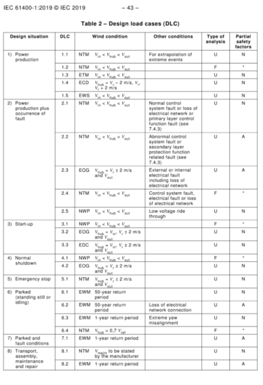
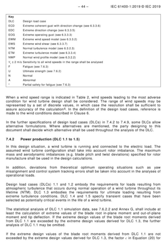
Table 2 – Design load cases (DLC)
Design situation | DLC | Wind condition | Other conditions | Type of an alysis | Partial safety factors |
1) Power production | 1.1 | NTM Vin <Vhub< span> <Vout< span> </Vout<> </Vhub<> | For extrapolation of extreme events | U | N |
| 1.2 | NTM Vin <Vhub< span> <Vout< span> </Vout<> </Vhub<> | | F | * |
| 1.3 | ETM Vin <Vhub< span> <Vout< span> </Vout<> </Vhub<> | | U | N |
| 1.4 | ECD Vhub=Vr−2 m/s, Vr, Vr+2 m/s | | U | N |
| 1.5 | EWS Vin <Vhub< span> <Vout< span> </Vout<> </Vhub<> | | U | N |
2) Power production plus occurrence of fault | 2.1 | NTM Vin <Vhub< span> <Vout< span> </Vout<> </Vhub<> | Normal control system fault or loss of electrical network or primary layer control function fault (see 7.4.3) | U | N |
| 2.2 | NTM Vin <Vhub< span> <Vout< span> </Vout<> </Vhub<> | Abnormal control system fault or secondary layer protection function related fault (see 7.4.3) | U | A |
| 2.3 | EOG Vhub=Vr±2 m/s and Vout | External or internal electrical fault including loss of electrical network | U | A |
| 2.4 | NTM Vin <Vhub< span> <Vout< span> </Vout<> </Vhub<> | Control system fault, electrical fault or loss of electrical network | F | * |
| 2.5 | NWP Vin <Vhub< span> <Vout< span> </Vout<> </Vhub<> | Low voltage ride through | U | N |
3) Start-up | 3.1 | NWP Vin <Vhub< span> <Vout< span> </Vout<> </Vhub<> | | F | * |
| 3.2 | EOG Vhub=Vin, Vr±2 m/s and Vout | | U | N |
| 3.3 | EDC Vhub=Vin, Vr±2 m/s and Vout | | U | N |
4) Normal shutdown | 4.1 | NWP Vin <Vhub< span> <Vout< span> </Vout<> </Vhub<> | | F | * |
| 4.2 | EOG Vhub=Vr±2 m/s and Vout | | U | N |
5) Emergency stop | 5.1 | NTM Vhub=Vr±2 m/s and Vout | | U | N |
6) Parked (standing still or idling) | 6.1 | EWM 50-year return period | | U | N |
| 6.2 | EWM 50-year return period | Loss of electrical network connection | U | A |
| 6.3 | EWM 1-year return period | Extreme yaw misalignment | U | N |
| 6.4 | NTM Vhub<0.7 Vref | | F | * |
7) Parked and fault conditions | 7.1 | EWM 1-year return period | | U | A |
8) Transport, assembly, maintenance and repair | 8.1 | NTM Vmaj to be stated by the manufacturer | | U | N |
| 8.2 | EWM 1-year return period | | U | A |
Key
DLC Design load case
ECD Extreme coherent gust with direction change (see 6.3.3.6)
EDC Extreme direction change (see 6.3.3.5)
EOG Extreme operating gust (see 6.3.3.3)
EWM Extreme wind speed model (see 6.3.3.2)
EWS Extreme wind shear (see 6.3.3.7)
NTM Normal turbulence model (see 6.3.2.3)
ETM Extreme turbulence model (see 6.3.3.4)
NWP Normal wind profile model (see 6.3.2.2)
Vr±2m/s Sensitivity to all wind speeds in the range shall be a nalysed
F Fatigue (see 7.6.3)
U Ultimate strength (see 7.6.2)
N Normal
A Abnormal
* Partial safety for fatigue (see 7.6.3)
When a wind speed range is indicated in Table 2, wind speeds leading to the most adverse condition for wind turbine design shall be considered. The range of wind speeds may be represented by a set of discrete values, in which case the resolution shall be sufficient to assure accuracy of the calculation⁶. In the definition of the design load cases, reference is made to the wind conditions described in Clause 6.
In the further specifications of design load cases (DLCs) in 7.4.2 to 7.4.9, some DLCs allow alternative formulations. Where alternatives are mentioned, the party designing to this document shall decide which alternative shall be used throughout the an alysis of the DLC.
7.4.2 Power production (DLC 1.1 to 1.5)
In this design situation, a wind turbine is running and connected to the electric load. The assumed wind turbine configuration shall take into account rotor imbalance. The maximum mass and aerodynamic imbalances (e.g. blade pitch and twist deviations) specified for rotor manufacture shall be used in the design calculations.
In addition, deviations from theoretical optimum operating situations such as yaw misalignment and control system tracking errors shall be taken into account in the an alyses of operational loads.
Design load cases (DLCs) 1.1 and 1.2 embody the requirements for loads resulting from atmospheric turbulence that occurs during normal operation of a wind turbine throughout its lifetime (NTM). DLC 1.3 embodies the requirements for ultimate loading resulting from extreme turbulence conditions. DLC 1.4 and 1.5 specify transient cases that have been selected as potentially critical events in the life of a wind turbine.
The statistical an alysis of DLC 1.1 simulation data, see 7.6.2 and Annex G, shall include at least the calculation of extreme values of the blade root in-plane moment and out-of-plane moment and tip deflection. If the extreme design values of the blade root moments derived from DLC 1.1 are exceeded by the extreme design values derived for DLC 1.3, the further an alysis of DLC 1.1 may be omitted.
If the extreme design values of the blade root moments derived from DLC 1.1 are not exceeded by the extreme design values derived for DLC 1.3, the factor c in Equation (20) for the extreme turbulence model used in DLC 1.3 may be increased until the extreme design values of the blade root moments computed in DLC 1.3 are equal to or exceed the relevant values derived from DLC 1.1. The characteristic values of the loads relevant for other turbine components may be determined from this a nalysis based on DLC 1.3 with the increased c-value. As an alternative to this a nalysis, the appropriate characteristic values of all load components relevant for each specific turbine component may be directly determined or extrapolated from the simulation.
表 2 — 设计荷载工况(DLC)
设计工况 | DLC 编号 | 风况条件 | 其他条件 | 分析类型 | 分项安全系数类别 |
1)正常发电 | 1.1 | NTM 切入风速<轮毂风速<切出风速 | 用于极端事件外推分析 | U | N(正常) |
| 1.2 | NTM 切入风速<轮毂风速<切出风速 | | F | *(疲劳分项系数) |
| 1.3 | ETM 切入风速<轮毂风速<切出风速 | | U | N(正常) |
| 1.4 | ECD 轮毂风速 = 额定风速−2m/s、额定风速、额定风速 + 2m/s | | U | N(正常) |
| 1.5 | EWS 切入风速<轮毂风速<切出风速 | | U | N(正常) |
2)发电叠加故障工况 | 2.1 | NTM 切入风速<轮毂风速<切出风速 | 常规控制系统故障、电网失电或第一层控制功能故障(见 7.4.3) | U | N(正常) |
| 2.2 | NTM 切入风速<轮毂风速<切出风速 | 异常控制系统故障或第二层保护功能相关故障(见 7.4.3) | U | A(异常) |
| 2.3 | EOG 轮毂风速 = 额定风速 ±2m/s、切出风速 | 内部 / 外部电气故障,包含电网失电 | U | A(异常) |
| 2.4 | NTM 切入风速<轮毂风速<切出风速 | 控制系统故障、电气故障或电网失电 | F | *(疲劳分项系数) |
| 2.5 | NWP 切入风速<轮毂风速<切出风速 | 低电压穿越 | U | N(正常) |
3)启动 | 3.1 | NWP 切入风速<轮毂风速<切出风速 | | F | *(疲劳分项系数) |
| 3.2 | EOG 轮毂风速 = 切入风速、额定风速 ±2m/s、切出风速 | | U | N(正常) |
| 3.3 | EDC 轮毂风速 = 切入风速、额定风速 ±2m/s、切出风速 | | U | N(正常) |
4)正常停机 | 4.1 | NWP 切入风速<轮毂风速<切出风速 | | F | *(疲劳分项系数) |
| 4.2 | EOG 轮毂风速 = 额定风速 ±2m/s、切出风速 | | U | N(正常) |
5)紧急停机 | 5.1 | NTM 轮毂风速 = 额定风速 ±2m/s、切出风速 | | U | N(正常) |
6)停机(静止或空转) | 6.1 | EWM 50 年一遇重现期 | | U | N(正常) |
| 6.2 | EWM 50 年一遇重现期 | 电网连接丢失 | U | A(异常) |
| 6.3 | EWM 1 年一遇重现期 | 极端偏航不对中 | U | N(正常) |
| 6.4 | NTM 轮毂风速<0.7 倍参考风速 | | F | *(疲劳分项系数) |
7)停机叠加故障工况 | 7.1 | EWM 1 年一遇重现期 | | U | A(异常) |
8)运输、组装、运维检修 | 8.1 | NTM 最大风速由制造商规定 | | U | N(正常) |
| 8.2 | EWM 1 年一遇重现期 | | U | A(异常) |
符号说明
DLC 设计荷载工况
ECD 带方向变化的极端相干阵风(见 6.3.3.6)
EDC 极端风向变化(见 6.3.3.5)
EOG 极端运行阵风(见 6.3.3.3)
EWM 极端风速模型(见 6.3.3.2)
EWS 极端风剪切(见 6.3.3.7)
NTM 正常湍流模型(见 6.3.2.3)
ETM 极端湍流模型(见 6.3.3.4)
NWP 正常风廓线模型(见 6.3.2.2)
Vr±2m/s 需分析该风速区间内全部风速对应的敏感性
F 疲劳荷载分析(见 7.6.3)
U 极限强度分析(见 7.6.2)
N 正常工况
A 异常工况
* 疲劳对应的分项安全系数(见 7.6.3)
当表 2 中标注风速区间时,应当选取使风力发电机组设计承受最不利条件的风速开展计算。该风速区间可以采用一系列离散风速值表征,离散取值间隔应当足以保证计算精度⁶。设计荷载工况定义均参考第 6 章规定的各类风况条件。
7.4.2~7.4.9 对各设计荷载工况(DLC)作出进一步规定,部分荷载工况允许选用多种计算方案。当条文给出多种可选方案时,依据本标准开展设计的单位应当选定一种方案,并在该荷载工况全部分析过程中统一采用。
7.4.2 正常发电工况(DLC 1.1~1.5)
该设计工况下,风力发电机组处于运行状态并接入电气负荷。所采用的机组模型应当考虑风轮不平衡效应;设计计算需采用风轮制造允许的最大质量不平衡与气动不平衡(例如叶片桨距、扭角偏差)。
除此之外,开展运行荷载分析时,还应当考虑偏离理论最优运行状态的各类偏差,例如偏航不对中、控制系统跟踪误差。
设计荷载工况 DLC1.1 与 1.2,规定了机组全生命周期正常运行时大气湍流引发荷载的相关要求(正常湍流模型 NTM);DLC1.3 规定极端湍流条件产生极限荷载的相关要求;DLC1.4 与 1.5 为瞬态工况,选取机组生命周期内具有潜在危险性的关键事件。
针对 DLC1.1 仿真数据开展统计分析(见 7.6.2 及附录 G),至少应当计算叶根面内弯矩、面外弯矩以及叶尖挠度的极值。若 DLC1.3 得到的叶根弯矩设计极值大于 DLC1.1 得到的极值,则可省略 DLC1.1 的后续分析。
若 DLC1.3 得到的叶根弯矩设计极值未超过 DLC1.1 得到的极值,则式 (20) 中的系数c可增大 DLC 1.3 中所使用的极端湍流模型,直至 DLC 1.3 计算得到的叶根弯矩极值等于或超过 DLC 1.1 中导出的相关值。对于风力机其他部件相关的荷载特征值,可基于采用增大后 c 值的 DLC 1.3 分析结果确定。作为该分析的替代方法,也可通过仿真直接确定或外推各特定风力机部件所需的所有相关荷载分量的特征值。
简单总结
本节给出 IEC 61400-1 标准核心荷载工况表,划分 8 大类机组设计工况,搭配对应的风模型、外部条件、极限或疲劳分析类型以及正常或异常分项安全系数;同时补充工况选取原则、风速取值要求,并针对发电工况(DLC1.1~1.5)说明建模要求、不平衡量考虑规则、湍流工况分工,以及 DLC1.1 与 DLC1.3 极值结果对比后的分析简化判定准则。
今天就学到这里,明天我们继续学习,每天十分钟大家一起学标准。