氢与一氧化碳燃烧小型详细化学反应机理测试

氢与一氧化碳燃烧小型详细化学反应机理测试(Testing a small detailed chemical-kinetic mechanism for the combustion of hydrogen and carbon monoxide)
摘要:
本文构建了适用于 H₂/CO 燃烧的小型详细化学反应机理,共 30 步基元反应、11 种组分,聚焦1000 K 以上、100 bar 以下、当量比 < 3工况。通过修正 H+OH+M、H+O₂+M 等关键反应速率,删除无效引发反应,新增 CO+O₂→CO₂+O 步骤,提升预测精度。经常压 / 高压层流火焰速度、对冲扩散火焰熄灭极限、激波管点火延迟多工况验证,模型与实验高度吻合。该机理结构精简、计算高效,不影响烃类燃料子机理兼容性,可为工程燃烧模拟提供可靠的 H₂/CO 基础反应模型。
Abstract
A relatively s mall detailed mechanis m has been developed for the combustion of various fuels, mainly hydrocar- bons, in air or oxygen-inert mixtures. This mechanis m has been tested previously for autoignition, premixed-flame burning velocities, and structures and extinction of diffusion flames and of partially premixed flames of many of these fuels. While submechanis ms for hydrogen and carbon monoxide are essential components of this mecha- nis m, thorough testing of the predictions of the mechanis m for these simpler fuels has not been performed recently. Such testing is reported here and leads to modifications of rate parameters for a few of the most important elemen- tary steps, as well as to deletion of one reaction and addition of another.
◎ 2005 The Combustion Institute. Published by Elsevier Inc. All rights reserved.
Keywords: Chemical-kinetic mechanis ms; Autoignition; Laminar burning velocities; Diffusion-flame extinction; Hydrogen; Carbon monoxide
1. Introduction
Because of limitations on computer capabilities, there is a need for detailed chemical-kinetic mecha- nis ms for combustion that are not too large. As an al- ternative to mechanis ms having thousands of elemen- tary steps, a mechanis m having less than 300 steps is being developed [1]. This simplification is achieved by restricting attention to temperatures above about 1000 K, pressures below about 100 bar, equivalence ratios less than about 3 in premixed systems, and strain rates greater than about 50 s_1 in nonpremixed or partially premixed systems. The simplifications * Corresponding author. Fax: +1 (858) 534 5354.
Because of limitations on computer capabilities, there is a need for detailed chemical-kinetic mecha- nis ms for combustion that are not too large. As an al- ternative to mechanis ms having thousands of elemen- tary steps, a mechanis m having less than 300 steps is being developed [1]. This simplification is achieved by restricting attention to temperatures above about 1000 K, pressures below about 100 bar, equivalence ratios less than about 3 in premixed systems, and strain rates greater than about 50 s_1 in nonpremixed or partially premixed systems. The simplifications then arise mainly from the unimportance of soot for- mation and cool-flame phenomena under these condi- tions.
Fuels that have been studied previously with this mechanis m include methane [2], ethane [3], ethylene [4], acetylene [5,6], propane [1], propene[1], propyne [1], allene [1], and methanol [7,8]. Tests also have been made recently for hydrogen autoignition [9], and some time ago premixed and diffusion flames of car- bon monoxide were addressed [10,11]. There have, however, been no recent tests for premixed hydrogen flames and no tests at all for autoignition of mixtures containing carbon monoxide. Since the hydrogen and carbon monoxide submechanis ms are essential to the mechanis ms of all of the other fuels, and since there is also substantial interest in these two fuels them-selves, testing of the mechanis m for them is com- pleted here.
Results from the present work on the submech- anis m for hydrogen and carbon monoxide are in- cluded in the larger mechanis m that extends through propane [1]. The comparisons to be reported lead to s mall revisions of rate parameters for a few el- ementary steps. The resulting steps and rate para- meters for this submechanis m are given in Table 1, in which all steps are considered to be reversible, with backward rates obtained from listed forward rates by use of equilibrium constants. The revisions improve agreements in the present comparisons, for the most part without significantly affecting previ- ous comparisons for methane, ethane, ethylene, and acetylene. The revised values are in agreement with those in some of the more recent literature, and the changes are well within fundamental uncertain- ties in rates of elementary steps. These uncertainties were considered for all of the steps, and possibili- ties of revising rate parameters for many additional steps were investigated but finally rejected as insuf- ficiently useful or not justified well enough from fundamental considerations. In addition, one reac- tion is deleted that has been demonstrated recently to be unlikely to occur, and one has been added that previously had been thought to be unimportant but was found to exert a s mall but noticeable ef- fect.
In the following sections comparisons are made first for premixed hydrogen systems, next for hydro- gen diffusion-flame extinction, then for burning ve- locities of premixed flames of carbon monoxide with different amounts of hydrogen, and finally for au- toignition of mixtures of carbon monoxide and hy- drogen. The rate-parameter revisions are discussed in connection with the test for which they are most rel- evant. The computations for the comparisons were performed with CHEMKIN [19]programs, although the FLAMEMaster program [20] was also employed to make sure that predictions from the two different programs were the same.
2. Hydrogen burning velocities
There is a wealth of data available for laminar flame speeds for hydrogen–air systems for a wide range of equivalence ratios at normal atmospheric pressure and initially room temperature. In the ear- liest predecessor of the present mechanis m for hy- drogen [21], comparisons were made with data taken prior to 1990. These results exhibited a great deal of scatter, but more recent data are much more accurate. The measurements that we judge to be most reliable were selected for comparisons in the present work.
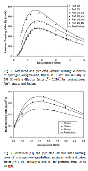
These include hydrogen–air data at 1 atm and an ini- tial temperature of 298 K for equivalence-ratio ranges of 0.23 to 4.5[22], 0.25to1.5[23], 0.4 to 4.0[24], and 0.6 to 4.5 [25]. These results are in remarkably good agreement with each other. In addition, for these same conditions good data are available [25]for hydrogen– oxygen mixtures diluted by argon and by helium at 1 atm, and also [24]at pressures up to 20 atm for this last diluent.
Figs. 1 and 2compare the present burning-velocity predictions with these data. The computational results were obtained with CHEMKIN 3.7 PREMIX includ- ing multicomponent diffusion and Soret effects but excluding radiant energy loss, which would decrease predicted burning velocities only slightly under these conditions. Throughout the present work, calculations also were made including radiant loss from H2O and CO2 bands in an optically thin approximation, and re- sults differed approximately by the thickness of the lines.
A dilution factor may be defined as f =[O2]/ ([O2]+[I]),
where the brackets denote concentrations and I stands for the inert; f = 0.214 in Fig. 1, and f = 0.08 in Fig. 2. The agreements between predictions and ex- periments are quite good in these figures, comparable with the agreements obtained previously [26] by a more complex mechanis m. Although measured burn- ing velocities in air for very lean mixtures consistently exceed predictions, the exceptionally strong tendency toward forming cellular flames under these conditions makes experiments very difficult and would tend to produce measured burning velocities that are higher than those of a planar, unstretched flame, to which the computations apply.
The s mall mechanis m originally had 22 elemen- tary steps for hydrogen combustion, but recent calcu- lations of potential–energy surfaces [27]show clearly that one of the two chain-initiation steps that had been included, namely H2 + O2 → 2OH, is highly unlikely, leaving only the reverse of step 12, H2 + O2 → HO2 + H, for initiation. The unlikely step therefore now is deleted. Although this step influ- enced autoignition times at higher temperatures, cou- pled with the other rate-parameter modifications in- dicated below, its deletion does not degrade reported [9] ignition-time comparisons. The comparisons in Figs. 1 and 2 therefore pertain to a 21-step hydro- gen combustion mechanis m, the first 21 entries in Ta- ble 1.
When the mechanis m was first tested against these data, it gave burning velocities noticeably higher than those shown in Fig. 1 for air over most of the equivalence-ratio range and much lower than shown in Fig. 2. The rate parameters therefore were reviewed again for all steps, and certain revisions were made on the basis of more recent literature and to obtain the agreements seen in Figs. 1 and 2.
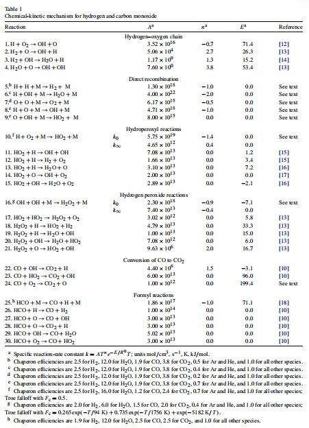
The rate of the recombination step 6, H + OH + M → H2O + M, was increased by about 80% to re- duce high-temperature hydrogen–air burning veloci-ties, on the basis of newer literature [28–30], which supports this revision, the listed rate being an average of the rates in the newer literature. The rate of step 11, HO2 + H → 2OH, had been decreased to reduce pre- dicted propane–air burning velocities [1], improving agreements, and that similarly helps for hydrogen–air
flames. Associated with this decrease, considerations
of rate and branching-ratio results [31,32] prompted recommending a corresponding reduction in the rate of step 12, HO2 + H → H2 + O2 [15]. The specific reaction-rate constant

with the recommended [15]parameter values listed as entry 12 in Table 1 is therefore now adopted for this step, improving agreements slightly for both burning velocities and autoignition times. Revision of the rate of step 17, 2HO2 → H2O2+ O2, was considered but rejected as not well justified at the high temperatures of interest.
All of the other changes that were made pertain to the three-body recombinations. Newer [13] rate pa- rameters were adopted for O + H + M → OH + M (entry 8 of Table 1) with the recommended chaperon efficiencies. The rate parameters for O + O + M → O2 + M (entry 7) also were taken from this refer- ence, although chaperon efficiencies of 0.2 were in- troduced for argon and helium to avoid employing separate reactions for these third bodies, the selected value representing an average over the temperature range of interest here (1000 to 2500 K). All rate pa- rameters are written consistently with a chaperon effi- ciency of unity for nitrogen. For step 5, H + H + M → H2 + M, the recommendation of Baulch et al. [16] was adopted; these authors give values only for argon as the chaperon, whose efficiency with respect to ni- trogen was assumed to be 0.5, slightly improving fuel- rich burning-velocity agreements in Fig. 1and result- ing in rates that lie between those of Li [26] and of the optimized mechanis m of Davis et al. [30], whose common relative efficiencies [26,30] were adopted. For reaction 9, O + OH + M → HO2 + M, chap- eron efficiencies are now introduced which are the same as those of O + H + M → OH + M, while the rate is slightly reduced (by 20%) from our pre- vious value [33]. The Troe [34] rate parameters and falloff recommendations for step 10, H + O2 + M → HO2 + M, for nitrogen as the bath gas (e.g., Fc = 0.5) were adopted, improving both burning-velocity agreement for high-pressure experiments with helium dilution and ignition-time agreement; Petrova and Williams [1] have a misprint in k0 for this step. To avoid having to introduce either a different rate ex- pression or temperature-dependent chaperon efficien- cies for argon as the bath gas for this reaction, just as was done for the other recombination processes discussed above, constant chaperon efficiencies were selected, a high value for water being used for agree- ment with measured autoignition times and diffusion- flame extinction by water addition, and a value for ar- gon being selected consistent with autoignition times. Finally, for step 16, OH + OH + M → H2O2 + M, the listed rate parameters [9] are obtained from those for nitrogen of Baulch et al. [35] (who write the re- action in the opposite direction) by use of equilib- rium constants, but the argon efficiency was decreased from 0.7 to 0.4, a better average, between 1000 and 2500 K, of the temperature-dependent recommenda- tion of Baulch et al. [35].
3. Hydrogen diffusion-flame extinction
The mechanis m with these updated rate parame- ters also was tested against counterflow diffusion- flame extinction experiments. Comparisons are shown in Figs. 3 and 4. The extinction strain-rate data in Fig. 3 [36] are seen to lie below the solid curve, calculated using CHEMKIN 3.7 OPDIFF with com- plete transport. Since there is an indication of inaccu- rate transport data for hydrogen (as well as helium) in the code [37], for comparison purposes the cal- culation also was performed with the Soret effects excluded, to obtain an idea of how important light- species transport may be. The results, shown by the dashed curve, agree better with the data, about as good as the agreement obtained [36] with an early version of the present mechanis m. In view of the nonnegligible influences of transport uncertainties for these experiments, until improved transport properties for hydrogen and helium can be incorporated into the computations, the agreement with the updated mech- anis m is considered acceptable.
Fig. 4 tests the influence of water addition on the extinction strain rate, employing data [38] against which other mechanis ms have been tested earlier. The agreement seen in this figure is somewhat better than found earlier [38], largely as a consequence of the in- creased chaperon efficiency for water in the 10, H + O2 + M → HO2 + M, which decreases the extinc- tion strain rate with increasing water concentrations more rapidly than predicted earlier. Although even better agreement can be obtained with falloff [39]for H2O different than that for N2, it was preferred to ac- cept the agreement shown for the sake of not having to treat the reaction with H2O as a separate reac- tion.

Fig. 3. Measured [36] and predicted extinction strain rate as a function of the mole fraction of hydrogen in a hydro- gen–nitrogen fuel mixture for a counterflow diffusion flame of the diluted fuel and air.

Fig. 4. Measured [38] and predicted extinction strain rate as a function of the mass fractions of water in the oxidizer stream for a counterflow diffusion flame having a hydro- gen–nitrogen mixture at room temperature as fuel (hydro- gen mole fractions between 0.28 and 0.29) and an oxy- gen–nitrogen–water mixture at 383 K (dilution f approxi- mately 0.1) as oxidizer.
4. Burning velocities of carbon monoxide
Since flames of carbon monoxide are dominated by hydrogen chemistry in practice, it is necessary only to add the three species CO, CO2, and HCO, along with nine additional reversible elementary steps, to the hydrogen–oxygen mechanis m, to obtain a work- able 30-step mechanis m among 11 species for the combustion of carbon monoxide, as seen in Table 1. Fig. 5 tests predictions of this mechanis m against re- cent burning-velocity data as a function of equiva- lence ratio for two different mixtures of hydrogen and carbon monoxide in air [40]. Fig. 6 similarly tests the dependence on the fraction of carbon monoxide in the fuel for stoichiometric mixtures [40]. The excellent agreement in these two figures indicates that slightly revised rate parameters for step 22, CO + OH → CO2+H[26], and revised rate parameters for step 23, CO + HO2 → CO2 + OH [41], motivated mainly by experiments at temperatures lower than those of in- terest here, are unnecessary for the present purposes; it was sufficient to retain the earlier [10] rates un- changed, which agree with results of a recent opti- mized mechanis m [30].

Fig. 5. Measured [40] and predicted laminar burning veloc- ities as functions of the equivalence ratio for two different mixtures of hydrogen and carbon monoxide in air at 1 atm and initially at 298 K.

Fig. 6. Measured [40]and predicted laminar burning veloci- ties of stoichiometric fuel–air mixtures at 1 atm and initially at 298 K, as a function of the percentage of carbon monox- ide in a fuel consisting of a mixture of hydrogen and carbon monoxide.

Fig. 7. Measured [42]and predicted laminar burning veloci- ties at 1 atm and initially at 298 K, as functions of the initial fuel mole fraction of carbon monoxide X CO at various dilu- tions f, for flames of carbon monoxide with initial hydrogen mole fraction XH2= 0.015(X CO+ XH2+ XH2O).
5. Autoignition of carbon monoxide
The mechanis m has not been tested previously for autoignition of mixtures of carbon monoxide and hy- drogen, even though there are shock-tube data [43, 44] on which such tests can be made. These tests were performed here using the homogeneous, adia- batic, isochoric option of CHEMKIN 3.7 AURORA.
Fig. 8 shows comparisons with one set of data [43] based on three different definitions of ignition times, all derived from profiles of the measured concentra- tion of carbon dioxide.Fig. 9shows comparisons with another set of data [44] at lower pressure, based on a different ignition-time criterion. In all comparisons,

Fig. 8. Measured [43]and predicted ignition times of a mix- ture of 12.15% CO, 0.05% H2, 1.0% O2, and 86.8% Ar by volume at pressures between 1.4 and 2.2 atm, accord- ing to three different definitions of the ignition times based on concentration–time profiles of carbon dioxide, namely, the time t1 of the zero intercept of the maximum-slope straight line, the time t2 at which the concentration is 1016 molecules/cm3 , and the time t3 at which the concen- tration is 3 × 10¹⁶ molecules/cm3.

Fig. 9. Measured [44] and predicted ignition times, defined as hydroxyl concentrations reaching 2.5 × 10_10 mol/cm3 , for a mixture of 3% CO, 1% H2, 5% O2, and 91% Ar by volume, at pressures between 0.15 and 0.30 atm.
the computational and experimental ignition-time cri- teria are the same. The agreements are comparable with or better than those obtained [1,4,5]for other fu- els; they are excellent in Fig. 8, while the predicted slope is a little higher than the average experimental data in Fig. 9. The experiments in this last figure were performed over a range of pressures, with values of the pressure not specified for each specific data point, and for each point it is possible to select a value of the pressure within the range that produces agreement between the prediction and the measurement. It is un- clear whether the noticeably greater theoretical slope, which agrees with the slope of Li [26], should be at- tributable to erroneous values of rate parameters or to systematic experimental error, which becomes more difficult to avoid at these low pressures in shock tubes of the dimensions employed.
It was found that although step 24, CO + O2 → CO2 + O, has no measurable influences on burning velocities and had not been retained previously as part of the mechanis m, it does have a noticeable influ- ence on these ignition times at low hydrogen content, contributing to initiation. This step therefore is now added to the mechanis m, with rate parameters giving half the rate recommended by Tsang and Hampson [45]. This selection improves agreements somewhat in Fig. 8 and lies in the range of other values in the literature, even lower rates having been reported [46].
6. Conclusions
The present study has led to a few revisions of rate parameters for elementary steps in the mecha- nis m for hydrogen and to deletion of a hydrogen initi- ation step and addition of an initiation step for carbon monoxide. s mall increases in three-body recombina- tion rates for certain steps and some changes in chap- eron efficiencies were identified. With these alter- ations, reasonable agreement is obtained with avail- able measured burning velocities, diffusion-flame ex- tinction conditions, and autoignition times. The sub- mechanis m for hydrogen and carbon monoxide ap- pearing in Table 1 thus is judged acceptable for use in future studies.
Acknowledgment
This work was supported by the National Science Foundation through Grant CTS 0129562.
References
[1] M.V. Petrova, F.A. Williams, Combust. Flame (2005), in press.
[2] S.C. Li, F.A. Williams, Combust. Flame 118 (1999) 399–414.
[3] M.M.Y. Waly, S.C. Li, F.A. Williams, J. Eng. Gas Tur- bine Power 122 (2000) 651–658.
[4] B. Varatharajan, F.A. Williams, J. Propul. Power 18 (2002) 344–351.
[5] M.M.Y. Waly, S.C. Li, F.A. Williams, Proc. Combust. Inst. 28 (2000) 2005–2012.
[6] B. Varatharajan, F.A. Williams, Combust. Flame 124 (2001) 624–645.
[7] S.C. Li, F.A. Williams, Proc. Combust. Inst. 26 (1996) 1017–1024.
[8] S.C. Li, F.A. Williams, Proc. Combust. Inst. 27 (1998) 485–493.
[9] G. Del Alamo, F.A. Williams, A.L. Sanchez, Combust. Sci. Technol. 176 (2004) 1599–1626.
[10] M.L. Rightley, F.A. Williams, Combust. Sci. Tech- nol. 125 (1997) 181–200.
[11] M.L. Rightley, F.A. Williams, Combust. Flame 101 (1995) 287–301.
[12] D.A. Masten, R.K. Hanson, C.T. Bowman, J. Phys. Chem. 94 (1990) 7119–7128.
[13] R.A. Yetter, F.L. Dryer, H. Rabitz, Combust. Sci. Tech- nol. 79 (1991) 97–128.
[14] M.D. s mooke, J. Comput. Phys. 48 (1982) 72–105.
[15] M.A. Mueller, T.J. Kim, R.A. Yetter, F.L. Dryer, Int. J. Chem. Kinet. 31 (1999) 113–125.
[16] D.L. Baulch, C.J. Cobos, R.A. Cox, C. Esser, P. Frank, Th. Just, J.A. Kerr, M.J. Pilling, J. Troe, R.W. Walker, J. Warnatz, J. Phys. Chem. Ref. Data 21 (1992) 411– 734.
[17] J. Warnatz, in: W.C. Gardiner (Ed.), Combustion Chemistry, Springer-Verlag, Berlin, 1984, pp. 197–360.
[18] R.P. Lindstedt, G. Skevis, Combust. Sci. Technol. 125 (1997) 73–137.
[19] R.J. Kee, F.M. Rupley, J.A. Miller, M.E. Coltrin, J.F. Grcar, E. Meeks, H.K. Moffat, A.E. Lutz, G. Dixon- Lewis, M.D. s mooke, J. Warnatz, G.H. Evans, R.S. Larson, R.E. Mitchell, L.R. Petzold, W.C. Reynolds, M. Caracotsios, W.E. Stewart, P. Glarborg, C. Wang, O. Adigun, W.G. Houf, C.P. Chou, S.F. Miller, CHEMKIN Collection, Release 3.7.1, Reaction Design, San Diego, CA, 2003.
[20] H. Pitsch, M.S. thesis, RWTH Aachen, Germany, 1993.
[21] G. Balakrishnan, F.A. Williams, J. Propul. Power 10 (1994) 434–437.
[22] D.R. Dowdy, D.B. s mith, S.C. Taylor, A. Williams, Proc. Combust. Inst. 23 (1990) 325–332.
[23] F.N. Egolfopoulos, C.K. Law, Proc. Combust. Inst. 23 (1990) 333–340.
[24] S.D. Tse, D.L. Zhu, C.K. Law, Proc. Combust. Inst. 28 (2000) 1793–1800.
[25] O.C. Kwon, G.M. Faeth, Combust. Flame 124 (2001) 590–610.
[26] J. Li, Ph.D. thesis, Princeton University, 2004.
[27] J.V. Michael, J.W. Sutherland, L.B. Harding, A.F. Wag- ner, Proc. Combust. Inst. 28 (2000) 1471–1478.
[28] J. Li, Z. Zhao, A. Kazakov, F.L. Dryer, Int. J. Chem. Kinet. 36 (2004) 566–575.
[29] O.M. Conaire, H.J. Curran, J.M. Simmie, W.J. Pitz, C.K. Westbrook, Int. J. Chem. Kinet. 36 (2004) 603– 622.
[30] S.G. Davis, A.V. Joshi, H. Wang, F. Egolfopoulos, Proc. Combust. Inst. 30 (2005) 1283–1292.
[31] H. Hippler, J. Troe, J. Willner, J. Chem. Phys. 93 (1990) 1755–1760.
[32] R.R. Baldwin, M.E. Fuller, J.S. Hillman, D. Jackson, R.W. Walker, Trans. Faraday Soc. 70 (1974) 635–641.
[33] E. Gutheil, G. Balakrishnan, F.A. Williams, in: N. Pe- ters, B. Rogg (Eds.), Reduced Kinetic Mechanis ms for Applications in Combustion Systems, Springer-Verlag, Berlin, 1993, Chap. 11.
[34] J. Troe, Proc. Combust. Inst. 28 (2000) 1463–1469.
[35] D.L. Baulch, C.J. Cobos, R.A. Cox, C. Esser, P. Frank, Th. Just, J.A. Kerr, M.J. Pilling, J. Troe, R.W. Walker, J. Warnatz, J. Phys. Chem. Ref. Data 23 (1994) 847– 1033.
[36] G. Balakrishnan, D. Trees, F.A. Williams, Combust. Flame 98 (1994) 123–126.
[37] P. Paul, J. Warnatz, Proc. Combust. Inst. 27 (1998) 495– 504.
[38] R. Seiser, K. Seshadri, Proc. Combust. Inst. 30 (2005) 407–414.
[39] R.W. Bates, D.M. Golden, R.K. Hanson, C.T. Bowman, Phys. Chem. Chem. Phys. 3 (2001) 2337–2342.
[40] I.C. McLean, D.B. s mith, S.C. Taylor, Proc. Combust. Inst. 25 (1994) 749–757.
[41] M.A. Mueller, R.A. Yetter, F.L. Dryer, Int. J. Chem. Kinet. 31 (1999) 705–724.
[42] B. Lewis, G. von Elbe, Combustion, Flames, and Ex- plosions of Gases, third ed., Academic Press, New York, 1987, p. 398.
[43] A.M. Dean, D.C. Steiner, E.E. Wang, Combust. Flame 32 (1978) 73–83.
[44] W.C. Gardiner, M. McFarland, K. Morinaga, T. Take- yama, B.F. Walker, J. Phys. Chem. 75 (1971) 1504– 1509.
[45] W. Tsang, R.F. Hampson, J. Phys. Chem. Ref. Data 15 (1986) 1087–1276.
[46] A.M. Dean, G.B. Kistiakowsky, J. Chem. Phys. 54 (1971) 1718–1725.
免责声明:
本页面/内容部分素材来源于互联网公 开 信 息,旨在传递更多信息,不代表本平台立场。
版权归原作者或机构所有,如涉及侵权,请通过平台联系我们,我们将在核实后第一时间处理。
本平台对转载内容的真实性、准确性不作任何保证,用户需自行判断并承担使用风险。