Design Compiler(DC)逻辑综合工具权威用户手册电子书545页

Design Compiler(DC)逻辑综合工具权威用户手册(Design Compiler User Guide Version H-2013.03)
摘要:
本文是 Synopsys Design Compiler H-2013.03 版官方用户指南,系统讲解数字逻辑综合全流程。内容涵盖工具基础操作、库配置、设计读入与层级管理、环境与约束定义、时序 / 面积 / 功耗优化及问题调试。详细介绍 Topographical 物理感知综合、多角多模式(MCMM)、接口逻辑模型(ILM)、层次化抽象与 UPF 低功耗流程,支持自上而下 / 自下而上混合编译策略。指南包含完整命令语法、约束设置、时序修复、物理约束导入与结果分析方法,配套工程案例与脚本规范,为数字 IC 前端工程师提供从 RTL 到门级网表的标准化综合实践指导。
Design Compiler®
User Guide
Version H-2013.03, March 2013

Copyright Notice and Proprietary Information
Copyright ◎ 2013 Synopsys, Inc. All rights reserved. This software and documentation contain confidential and proprietary information that is the property of Synopsys, Inc. The software and documentation are furnished under a license agreement and may be used or copied only in accordance with the terms of the license agreement. No part of the software and documentation may be reproduced, trans mitted, or translated, in any form or by any means, electronic, mechanical, manual, optical, or otherwise, without prior written permission of Synopsys, Inc., or as expressly provided by the license agreement.
Destination Control Statement
All technical data contained in this publication is subject to the export control laws of the United States of America.
Disclosure to nationals of other countries contrary to United States law is prohibited. It is the reader's responsibility to determine the applicable regulations and to comply with them.
Disclaimer
SYNOPSYS, INC., AND ITS LICENSORS MAKE NO WARRANTY OF ANY KIND, EXPRESS OR IMPLIED, WITH REGARD TO THIS MATERIAL, INCLUDING, BUT NOT LIMITED TO, THE IMPLIED WARRANTIES OF MERCHANTABILITY AND FITNESS FOR A PARTICULAR PURPOSE.
Trademarks
Synopsys and certain Synopsys product names are trademarks of Synopsys, as set forth at http://www.synopsys.com/Company/Pages/Trademarks.aspx.
All other product or company names may be trademarks of their respective owners.
Synopsys, Inc.
700 E. Middlefield Road Mountain View, CA 94043 www.synopsys.com
Copyright Statement for the Command-Line Editing Feature
Copyright ◎ 1992, 1993 The Regents of the University of California. All rights reserved. This code is derived from software contributed to Berkeley by Christos Zoulas of Cornell University.
Redistribution and use in source and binary forms, with or without modification, are permitted provided that the following conditions are met:
1. Redistributions of source code must retain the above copyright notice, this list of conditions and the following disclaimer.
2. Redistributions in binary form must reproduce the above copyright notice, this list of conditions and the following disclaimer in the documentation and/or other materials provided with the distribution.
3. All advertising materials mentioning features or use of this software must display the following acknowledgement: This product includes software developed by the University of California, Berkeley and its contributors.
4. Neither the name of the University nor the names of its contributors may be used to endorse or promote products derived from this software without specific prior written permission.
THIS SOFTWARE IS PROVIDED BY THE REGENTS AND CONTRIBUTORS "AS IS" AND ANY EXPRESS OR
IMPLIED WARRANTIES, INCLUDING, BUT NOT LIMITED TO, THE IMPLIED WARRANTIES OF
MERCHANTABILITY AND FITNESS FOR A PARTICULAR PURPOSE ARE DISCLAIMED. IN NO EVENT SHALL THE REGENTS OR CONTRIBUTORS BE LIABLE FOR ANY DIRECT, INDIRECT, INCIDENTAL, SPECIAL,
EXEMPLARY, OR CONSEQUENTIAL DAMAGES (INCLUDING, BUT NOT LIMITED TO, PROCUREMENT OF
SUBSTITUTE GOODS OR SERVICES; LOSS OF USE, DATA, OR PROFITS; OR BUSINESS INTERRUPTION) HOWEVER CAUSED AND ON ANY THEORY OF LIABILITY, WHETHER IN CONTRACT, STRICT LIABILITY, OR TORT (INCLUDING NEGLIGENCE OR OTHERWISE) ARISING IN ANY WAY OUT OF THE USE OF THIS
SOFTWARE, EVEN IF ADVISED OF THE POSSIBILITY OF SUCH DAMAGE.
Copyright Statement for the Line-Editing Library
Copyright ◎ 1992 Simmule Turner and Rich Salz. All rights reserved.
This software is not subject to any license of the American Telephone and Telegraph Company or of the Regents of the University of California.
Permission is granted to anyone to use this software for any purpose on any computer system, and to alter it and redistribute it freely, subject to the following restrictions:
1. The authors are not responsible for the consequences of use of this software, no matter how awful, even if they arise from flaws in it.
2. The origin of this software must not be misrepresented, either by explicit claim or by omission. Since few users ever read sources, credits must appear in the documentation.
3. Altered versions must be plainly marked as such, and must not be misrepresented as being the original software. Since few users ever read sources, credits must appear in the documentation.
4. This notice may not be removed or altered.
Preface
This preface includes the following sections:
• About This Manual
• Customer Support
About This Manual
The Design Compiler User Guide provides basic synthesis information for users of the Design Compiler tools. This manual describes synthesis concepts and commands, and presents examples for basic synthesis strategies.
This manual does not cover asynchronous design, I/O pad synthesis, test synthesis, simulation, or back-annotation of physical design information.
The information presented here supplements the Synopsys synthesis reference manuals but does not replace them. See other Synopsys documentation for details about topics not covered in this manual.
This manual supports the Synopsys synthesis tools, whether they are running under the UNIX operating system or the Linux operating system. The main text of this manual describes UNIX operation.
Audience
This manual is intended for logic designers and engineers who use the Synopsys synthesis tools with the VHDL or Verilog hardware description language (HDL). Before using this manual, you should be familiar with the following topics:
• High-level design techniques
• ASIC design principles
• Timing a nalysis principles
• Functional partitioning techniques
Related Publications
For additional information about Design Compiler, see the documentation on SolvNet at the following address:
https://solvnet.synopsys.com/DocsOnWeb
You might also want to see the documentation for the following related Synopsys products:
• Design Vision
• DesignWare components
• DFT Compiler and DFTMAX
• DC Explorer
• PrimeTime
• Power Compiler
• HDL Compiler
• IC Compiler
Release Notes
Information about new features, changes, enhancements, known limitations, and resolved Synopsys Technical Action Requests (STARs) is available in the Design Compiler Release Notes in SolvNet.
To see the Design Compiler Release Notes,
1. Go to the Download Center on SolvNet located at the following address:
https://solvnet.synopsys.com/DownloadCenter
2. Select Design Compiler, and then select a release in the list that appears.
Conventions
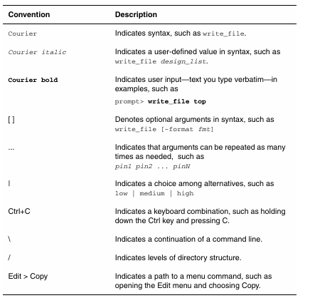
The following conventions are used in Synopsys documentation.
Customer Support
Customer support is available through SolvNet online customer support and through contacting the Synopsys Technical Support Center.
Accessing SolvNet
SolvNet includes a knowledge base of technical articles and answers to frequently asked questions about Synopsys tools. SolvNet also gives you access to a wide range of Synopsys online services including software downloads, documentation, and technical support.
To access SolvNet, go to the following address:
If prompted, enter your user name and password. If you do not have a Synopsys user name and password, follow the instructions to register with SolvNet.
If you need help using SolvNet, click HELP in the top-right menu bar.
Contacting the Synopsys Technical Support Center
If you have problems, questions, or suggestions, you can contact the Synopsys Technical Support Center in the following ways:
• Open a support case to your local support center online by signing in to SolvNet at https://solvnet.synopsys.com, clicking Support, and then clicking “Open A Support Case.”
• Send an e-mail message to your local support center.
❍ E-mail support_center@synopsys.com from within North America.
❍ Find other local support center e-mail addresses at
http://www.synopsys.com/Support/GlobalSupportCenters/Pages
• Telephone your local support center.
❍ Call (800) 245-8005 from within North America.
❍ Find other local support center telephone numbers at
http://www.synopsys.com/Support/GlobalSupportCenters/Pages
1 Introduction to Design Compiler
The Design Compiler tool is the core of the Synopsys synthesis products. Design Compiler optimizes designs to provide the s mallest and fastest logical representation of a given function. It comprises tools that synthesize your HDL designs into optimized, technology-dependent, gate-level designs. It supports a wide range of flat and hierarchical design styles and can optimize both combinational and sequential designs for speed, area, and power.
Design Compiler also provides topographical technology, which allows you to accurately predict post-layout timing, area, and power during RTL synthesis without the need for timing approximations based on wire load models. It uses Synopsys placement and optimization technologies to drive accurate timing prediction within synthesis, ensuring better correlation with the final physical design.
In addition, Design Compiler provides the Design Compiler Graphical tool, which optimizes multicorner-multimode designs and allows you to create and modify floorplans using floorplan exploration. The tool also reduces routing congestion, and it improves area correlation with IC Compiler and runtime in IC Compiler.
For an overview of Design Compiler, see
• Design Compiler in the Design Flow
• High-Level Design Flow Tasks
• Design Compiler Family
Design Compiler in the Design Flow
You use Design Compiler for logic synthesis, which is the process of converting a design description written in a hardware description language, such as Verilog or VHDL, into an optimized gate-level netlist mapped to a specific logic library. When the synthesized design meets functionality, timing, power, and other design goals, you can pass the design to IC Compiler for physical implementation.
Even though the following terms have slightly different meanings, they are often used synonymously in the Design Compiler documentation:
• Synthesis is the process that generates a gate-level netlist for an IC design that has been defined with a hardware description language (HDL). Synthesis includes reading the HDL source code and optimizing the design created from that description.
• Optimization is the step in the synthesis process that implements a combination of library cells that best meet the functional, timing, area, and power requirements of the design.
• Compile is the Design Compiler process that executes the synthesis and optimization steps. After you read in the design and perform other necessary tasks, you run the compile_ultra or compile command to generate a gate-level netlist for the design.
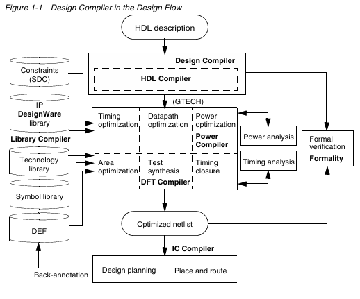
Figure 1-1 shows an overview of how Design Compiler fits into the design flow.
High-Level Design Flow Tasks
Figure 1-2 shows the high-level design flow from HDL coding to physical implementation in IC Compiler. The shaded areas indicate where the design exploration and synthesis tasks occur in the flow.
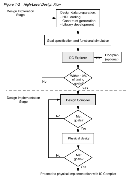
The synthesis design flow consists of the design exploration stage and the final design implementation stage. In the design exploration stage, you use DC Explorer to perform what-if an alyses of various design configurations early in the design cycle to speed the development of high-quality RTL and constraints and drive a faster, more convergent design flow. In the design implementation stage, you use the full power of Design Compiler to synthesize the design.
Using the high-level design flow shown in Figure 1-2, you perform the following tasks:
1. Write an HDL description of your design in Verilog or VHDL. Use good coding practices
to facilitate successful Design Compiler synthesis of the design.
2. Perform design exploration and functional simulation in parallel.
❍ In design exploration, use DC Explorer to (a) implement specific design goals, such as design rules and optimization constraints, (b) detect mis matches and missing constraints, and (c) resolve mis matches and design data inconsistencies.
You can also create and modify floorplans early in the design cycle with floorplan exploration.
❍ If design exploration fails to meet timing goals by more than 10 percent, modify your design goals and constraints, or improve the HDL code. Then repeat both design exploration and functional simulation.
❍ In functional simulation, determine whether the design performs the desired functions by using an appropriate simulation tool.
❍ If the design does not function as required, you must modify the HDL code and repeat both design exploration and functional simulation.
❍ Continue performing design exploration and functional simulation until the design is functioning correctly and is within 10 percent of the timing goals.
3. Perform design implementation synthesis by using Design Compiler to meet design goals.
After synthesizing the design into a gate-level netlist, verify that the design meets your goals. If the design does not meet your goals, generate and an alyze various reports to determine the techniques you might use to correct the problems.
4. After the design meets functionality, timing, power, and other design goals, proceed to the physical implementation stage in IC Compiler.
5. A nalyze the physical design’s performance by using back-annotated data. If the results do not meet design goals, resolve them in IC Compiler or return to step 3. If the results meet your design goals, you are finished with the design cycle.
See Also
• Design Compiler in the Design Flow
• Running a Synthesis Flow
Design Compiler Family
The Design Compiler family provides an integrated RTL synthesis solution to address today’s challenging IC designs. Using Design Compiler tools, you can
• Produce fast, area- and power-efficient IC designs using advanced optimizations and shared technology with IC Compiler place and route
• Predict, visualize, and alleviate routing congestion
• Perform floorplan exploration to create and modify design floorplans
• Explore design tradeoffs involving design constraints, such as timing, area, and power, under various loading, temperature, and voltage conditions
To learn about the Design Compiler family of products, see
• About DC Ultra
• About Design Compiler Graphical
• About DC Expert
• About DC Explorer
• About Design Vision
• About DesignWare Library
• About DFT Compiler and DFTMAX
• About Library Compiler
• About Power Compiler
About DC Ultra
At the core of the Synopsys RTL synthesis solution is DC Ultra. DC Ultra provides concurrent optimization of timing, area, power, and test for today’s high performance designs. DC Ultra includes topographical technology, which allows you to accurately predict post-layout timing, area, and power, ensuring better correlation with the final physical design.
DC Ultra provides the following features:
• Placement and optimization technologies that are shared with IC Compiler place and route to drive accurate timing and area prediction within synthesis, ensuring a better starting point for physical implementation
• Advanced delay optimization algorithms
• Advanced arithmetic optimization
• Integrated datapath partitioning and synthesis capabilities
• Advanced critical path resynthesis
• Register retiming, the process by which the tool moves registers through combinational gates to improve timing
• Advanced timing an alysis
• Support for multivoltage and multiple supply designs
• Infrastructure to support multicore execution for faster runtimes
• Support for hierarchical compile (top down or bottom up)
• Full and incremental compile techniques
• Sequential optimization for complex flip-flops and latches
• Command-line interface and graphical user interface
See Also
• Overview of Topographical Technology
About Design Compiler Graphical
In addition to DC Ultra capabilities, Design Compiler Graphical provides the following features:
• Optimization for multicorner-multimode designs
• Reduction of routing congestion during synthesis
• Improved area and timing correlation with IC Compiler
• Improved runtime and routability in IC Compiler
• Physical guidance technology, which includes enhanced placement and the capability to pass seed placement to IC Compiler to improve quality of results (QoR), correlation, and routability
• Ability to create and modify floorplans using floorplan exploration
See Also
• Using the Design Compiler Graphical Tool
About DC Expert
DC Expert provides optimization for area, timing, and power using wire load models for delay estimation.
DC Expert provides the following features:
• Hierarchical compile (top down or bottom up)
• Full and incremental compile techniques
• Sequential optimization for complex flip-flops and latches
• Time borrowing for latch-based designs
• Timing an alysis
• Command-line interface and graphical user interface
About DC Explorer
Developing new RTL and integrating it with third-party IP and many legacy RTL blocks can be a time-consuming process when designers lack a fast and efficient way to explore and improve the data, fix design issues, and create a better starting point for RTL synthesis.
DC Explorer overcomes these problems by allowing you to perform early RTL exploration, leading to a better starting point for RTL synthesis and accelerating design implementation.
DC Explorer provides the following features:
• Efficiently performs what-if an alyses of various design configurations early in the design cycle, even with incomplete design data, to speed the development of high quality RTL and constraints and drive a faster, more convergent design flow
• Generates an early netlist, which can be used to begin physical exploration in IC Compiler
• Creates and modifies floorplans very early in the design cycle with access to IC Compilerdesign planning
• Performs preliminary synthesis using only a s mall fraction of the time needed for full synthesis, yet gives you timing and area results typically within ten percent of the final results produced by Design Compiler in topographical mode
See Also
• The DC Explorer User Guide
About Design Vision
The Design Vision tool is the graphical user interface (GUI) for the Synopsys logic synthesis environment and provides an alysis tools for viewing and an alyzing designs at the generic technology (GTECH) level and gate level. The Design Vision main window provides menus and dialog boxes for running frequently used Design Compiler commands. It also provides graphical displays, such as histograms and schematics for visual ana lysis.
When you start Design Vision in topographical mode, the Design Vision layout window lets you an alyze physical constraints, timing, and congestion in your floorplan. A layout view displays floorplan constraints, critical timing paths, and congested areas in a single, flat view of the physical design. This information can help you to guide later optimization operations in Design Compiler and other Synopsys tools.
See Also
• The Design Vision User Guide
• Design Vision Help
About HDL Compiler
HDL Compiler translates Verilog or VHDL hardware language descriptions into a generic technology (GTECH) netlist, which is used by Design Compiler to create an optimized netlist.
See Also
• HDL Coding for Synthesis
• The HDL Compiler documentation
About DesignWare Library
A DesignWare library is a collection of reusable circuit-design building blocks, which are tightly integrated into the Synopsys synthesis environment. During synthesis, Design Compiler selects the right component with the best speed and area optimization from the DesignWare Library.
See Also
• The DesignWare Library documentation
About DFT Compiler and DFTMAX
The DFT Compiler tool is the Synopsys advanced test synthesis solution. It enables transparent implementation of design-for-test capabilities into the Synopsys synthesis flow without interfering with functional, timing, signal integrity, or power requirements.
DFTMAX compression provides synthesis-based adaptive scan technology to lower the cost of testing complex designs, particularly when fabricated with advanced process technologies. These deep-submicron (DS M) designs can have subtle manufacturing defects that are only detected by applying DS M tests, such as at-speed and bridging tests, in addition to stuck-at tests. The extra patterns needed to achieve high test quality for these designs can increase both the test time and the test data, resulting in higher test costs.
DFTMAX reduces these costs by delivering 10-100x test data and test time reduction with very low silicon area overhead. DFTMAX uniquely enables adaptive scan compression synthesis in Design Compiler and adaptive scan pattern generation in TetraMAX ATPG.
See Also
• The DFT Compiler and DFTMAX documentation
About Library Compiler
Library Compiler reads the description of an ASIC library from a text file and compiles the description into either an internal database (.db file format) or into VHDL libraries. The compiled database supports synthesis tools. The VHDL libraries support VHDL simulation tools.
See Also
• The Library Compiler documentation
About Power Compiler
The Power Compiler tool offers a complete methodology for power, including an alyzing and optimizing designs for static and dynamic power consumption.
See Also
• Power Optimization in Topographical Mode
• The Power Compiler User Guide
更多内容见附件
免责声明:
本页面/内容部分素材来源于互联网公 开 信 息,旨在传递更多信息,不代表本平台立场。
版权归原作者或机构所有,如涉及侵权,请通过平台联系我们,我们将在核实后第一时间处理。
本平台对转载内容的真实性、准确性不作任何保证,用户需自行判断并承担使用风险。