大家一起学标准之IEC61400-1(14)

点击听全文,今天大家继续一起学IEC61400-1。
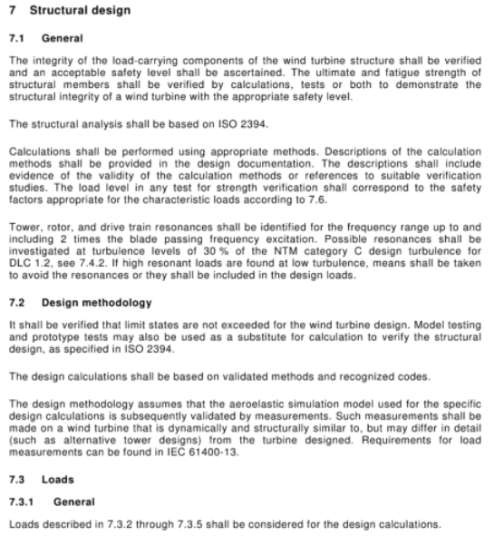
7 Structural design
7.1 General
The integrity of the load-carrying components of the wind turbine structure shall be verified and an acceptable safety level shall be ascertained. The ultimate and fatigue strength of structural members shall be verified by calculations, tests or both to demonstrate the structural integrity of a wind turbine with the appropriate safety level.The structural ana lysis shall be based on ISO 2394.Calculations shall be performed using appropriate methods. Descriptions of the calculation methods shall be provided in the design documentation. The descriptions shall include evidence of the validity of the calculation methods or references to suitable verification studies. The load level in any test for strength verification shall correspond to the safety factors appropriate for the characteristic loads according to 7.6.Tower, rotor, and drive train resonances shall be identified for the frequency range up to and including 2 times the blade passing frequency excitation. Possible resonances shall be investigated at turbulence levels of 30 % of the NTM category C design turbulence for DLC 1.2, see 7.4.2. If high resonant loads are found at low turbulence, means shall be taken to avoid the resonances or they shall be included in the design loads.
7.2 Design methodology
It shall be verified that limit states are not exceeded for the wind turbine design. Model testing and prototype tests may also be used as a substitute for calculation to verify the structural design, as specified in ISO 2394.The design calculations shall be based on validated methods and recognized codes.The design methodology assumes that the aeroelastic simulation model used for the specific design calculations is subsequently validated by measurements. Such measurements shall be made on a wind turbine that is dynamically and structurally similar to, but may differ in detail (such as alternative tower designs) from the turbine designed. Requirements for load measurements can be found in IEC 61400-13.
7.3 Loads
7.3.1 General
Loads described in 7.3.2 through 7.3.5 shall be considered for the design calculations.
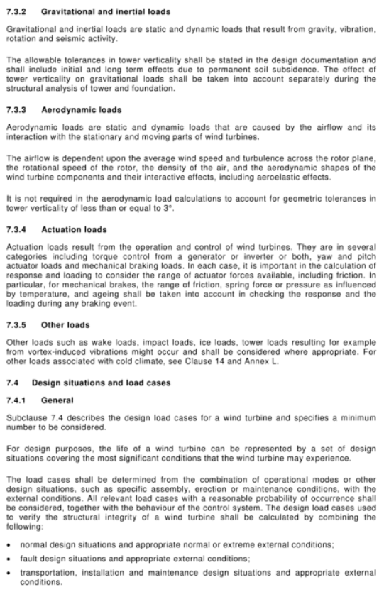
7.3.2 Gravitational and inertial loads
Gravitational and inertial loads are static and dynamic loads that result from gravity, vibration, rotation and seismic activity.The allowable tolerances in tower verticality shall be stated in the design documentation and shall include initial and long term effects due to permanent soil subsidence. The effect of tower verticality on gravitational loads shall be taken into account separately during the structural ana lysis of tower and foundation.
7.3.3 Aerodynamic loads
Aerodynamic loads are static and dynamic loads that are caused by the airflow and its interaction with the stationary and moving parts of wind turbines.The airflow is dependent upon the average wind speed and turbulence across the rotor plane, the rotational speed of the rotor, the density of the air, and the aerodynamic shapes of the wind turbine components and their interactive effects, including aeroelastic effects.It is not required in the aerodynamic load calculations to account for geometric tolerances in tower verticality of less than or equal to 3°.
7.3.4 Actuation loads
Actuation loads result from the operation and control of wind turbines. They are in several categories including torque control from a generator or inverter or both, yaw and pitch actuator loads and mechanical braking loads. In each case, it is important in the calculation of response and loading to consider the range of actuator forces available, including friction. In particular, for mechanical brakes, the range of friction, spring force or pressure as influenced by temperature, and ageing shall be taken into account in checking the response and the loading during any braking event.
7.3.5 Other loads
Other loads such as wake loads, impact loads, ice loads, tower loads resulting for example from vortex-induced vibrations might occur and shall be considered where appropriate. For other loads associated with cold climate, see Clause 14 and Annex L.
7.4 Design situations and load cases
7.4.1 General
Subclause 7.4 describes the design load cases for a wind turbine and specifies a minimum number to be considered.For design purposes, the life of a wind turbine can be represented by a set of design situations covering the most significant conditions that the wind turbine may experience.The load cases shall be determined from the combination of operational modes or other design situations, such as specific assembly, erection or maintenance conditions, with the external conditions. All relevant load cases with a reasonable probability of occurrence shall be considered, together with the behaviour of the control system. The design load cases used to verify the structural integrity of a wind turbine shall be calculated by combining the following:
·normal design situations and appropriate normal or extreme external conditions;
·fault design situations and appropriate external conditions;
·transportation, installation and maintenance design situations and appropriate external conditions.
If correlation exists between an extreme external condition and a fault situation, a realistic combination of the two shall be considered as a design load case.
Within each design situation, several design load cases shall be considered. As a minimum, the design load cases in Table 2 shall be considered. In that table, the design load cases are specified for each design situation by the description of the wind, electrical and other external conditions.
If the wind turbine controller can, during design load cases with a deterministic wind model, cause the wind turbine to shut down prior to reaching maximum yaw angle and/or wind speed, then it shall be shown that the turbine can reliably shut down under turbulent conditions with the same deterministic wind condition change.
Other design load cases shall be considered, if relevant to the structural integrity of the specific wind turbine design.
For each design load case, the appropriate type of an alysis is stated by "F" and "U" in Table 2. "F" refers to an alysis of fatigue loads, to be used in the assessment of fatigue strength. "U" refers to the an alysis of ultimate loads, with reference to material strength, blade tip deflection and structural stability.
The design load cases indicated with "U" are classified as normal (N) or abnormal (A). Normal design load cases are expected to occur frequently. The turbine is in a normal state or may have experienced minor faults or abnormalities. Abnormal design situations are less likely to occur. They usually correspond to design situations with severe faults that result in the activation of system protection functions. The type of design situation, N or A, determines the partial safety factor γf to be applied to the ultimate loads. These factors are given in Table 3.
7 结构设计
7.1 概述
应验证风力机承载构件的完整性,并确定可接受的安全水平。应通过计算、试验或二者相结合的方式验证构件的极限强度与疲劳强度,证明风力机结构具备相应的安全完整性。
结构分析应依据 ISO 2394。计算应采用合适的方法,设计文件中应当提供计算方法说明;说明内容需包含计算方法有效性证明,或引用适用的验证研究。任何强度验证试验中的荷载水平,均应采用 7.6 规定的、对应特征荷载的安全系数。
应识别塔筒、风轮与传动链在最高至 2 倍叶片通过频率激励区间内的共振。需在 DLC 1.2 工况、NTM C 类湍流 30% 湍流强度条件下,研究潜在共振;若在低湍流工况下发现较大共振荷载,应当采取措施规避共振,或将共振荷载纳入设计荷载。
7.2 设计方法
设计需验证风力机不会超出各类极限状态。按照 ISO 2394 规定,模型试验与样机试验可替代计算开展结构设计验证。
设计计算应当采用经过验证的方法与公认规范。该设计方法假定:特定设计计算所使用的气动弹性仿真模型后续需通过实测进行验证。实测对象为动力学与结构形式相似(细节可存在差异,例如塔筒方案不同)的风力机;荷载测量相关要求见 IEC 61400-13。
7.3 荷载
7.3.1 概述
设计计算应当考虑 7.3.2 至 7.3.5 所描述的各类荷载。
7.3.2 重力荷载与惯性荷载
重力荷载与惯性荷载是由重力、振动、旋转及地震作用产生的静荷载与动荷载。
塔筒垂直度允许偏差应在设计文件中明确,需包含初始偏差以及土体长期沉降带来的长期偏差。塔筒垂直度对重力荷载产生的影响,应当在塔筒与基础的结构分析中单独考虑。
7.3.3 气动荷载
气动荷载是气流与风力机静止、运动部件相互作用产生的静荷载与动荷载。气流条件取决于叶轮平面平均风速、湍流、风轮转速、空气密度、风力机构件气动外形及其耦合效应,包含气动弹性效应。若塔筒垂直度几何偏差不大于 3°,气动荷载计算时无需考虑该几何公差。
7.3.4 执行机构荷载
执行机构荷载由风力机运行与控制动作产生,包含发电机 / 变流器扭矩控制荷载、偏航与变桨执行机构荷载、机械制动荷载等类别。在开展结构响应与荷载计算时,均应当考虑执行机构可输出作用力范围(含摩擦力)。尤其对于机械制动器,在校核制动过程的结构响应与荷载时,应考虑温度、老化对摩擦力、弹簧力或压力区间带来的影响。
7.3.5 其他荷载
还可能存在尾流荷载、冲击荷载、覆冰荷载、由涡激振动引发的塔筒荷载等其他荷载,在适用情况下均需予以考虑。寒冷气候相关其他荷载参见第 14 章及附录 L。
7.4 设计工况与荷载工况
7.4.1 概述
第 7.4 条阐述风力机设计荷载工况,并规定最低需考虑的工况数量。
从设计角度,风力机全生命周期可由一组设计工况表征,覆盖机组可能遭遇的最关键条件。荷载工况由运行模式或其他设计工况(如装配、吊装、运维工况)与外部条件组合确定。所有具备合理发生概率的荷载工况均应予以考虑,同时结合控制系统行为开展分析。用于验证风力机结构完整性的设计荷载工况,通过以下内容组合计算得到:
·正常设计工况,搭配适用的正常或极端外部环境条件;
·故障设计工况,搭配适用的外部环境条件;
·运输、安装与运维设计工况,搭配适用的外部环境条件。
若极端外部条件与故障工况之间存在相关性,应将二者进行符合实际的组合,作为一项设计荷载工况。
每种设计工况下均应考虑若干设计荷载工况;最低限度必须考虑表 2 内所列荷载工况。表 2 中针对各设计工况,通过风况、电气条件与其他外部条件对设计荷载工况进行定义。
在确定性风模型对应的设计荷载工况中,若风力机控制器能够在达到最大偏航角度和 / 或风速之前实现停机,则必须证明:在具备同等确定性风况变化的湍流条件下,机组同样能够可靠完成停机。
若某些工况会影响特定风力机结构完整性,则还应额外考虑对应的设计荷载工况。
每个设计荷载工况对应的分析类型在表 2 中以 “F” 和 “U” 标识:“F” 代表疲劳荷载分析,用于疲劳强度评估;“U” 代表极限荷载分析,关联材料强度、叶尖挠度与结构稳定性。
标注 “U” 的设计荷载工况分为正常(N)或异常(A)两类。正常设计工况发生较为频繁,机组处于正常状态或仅存在轻微故障、异常;异常设计工况发生概率更低,通常对应出现严重故障、触发系统保护功能的工况。设计工况类型(N 或 A)决定极限荷载所采用的分项安全系数γf,相关系数见表 3。
简单总结
第七章为风机结构设计核心条款,规定结构完整性验证要求、设计方法与模型验证规则;划分重力惯性、气动、执行机构、其他四大类荷载;明确各类运行、故障、吊装运维等设计工况组合原则,区分疲劳分析 (F) 和极限分析 (U),并依据工况类别选用对应的分项安全系数。