风力涡轮机的气动性能

ABSTRACT:
Recent years have seen a rise in interest in sustainable energy sources because of the growing demand for energy, worries about the depletion of fossil fuel supplies, efforts to mitigate climate change, and global warming. Wind is one of the several sustainable energy sources along with solar, wave, geothermal, and tidal energy that has been shown to be a less expensive way to generate energy. Due to the construction of massive wind farms across the globe, wind power is the energy source with the quickest rate of growth. This has led to a great deal of research focused on wind and the development and advancement of technology to produce energy from wind. The paper deals with Computational Fluid Dynamic (CFD) ana lysis for the duct with series of wind turbines mounted on top of the Railway Trains. The purpose of the duct with series of wind turbines is to generate electricity while the train is running. This helps in generation of electricity by using renewable resources rather than using non-renewable resources. Here couple of variants of wind turbine arrangements were done and CFD an alysis is carried out to find the efficient system. The arrangement consists of 1 duct with 6 turbines and 2 ducts with 3 turbines.
1.Introduction
In our modern fast development of the technology, the electricity demand and consumption are increased in the world. Hence a renewable energy like solar, wind and fossil fuels are much required at the moment. In India, the major energy consumption are railways and manufacturing industries. Wind is a renewable source of energy; the wind can convert into the electricity. The speed of the wind can increase the power production through turbines. This paper brings a new possibility for the utilization of the generating power from the wind, for various electrical components inside a typical railway train through the batteries, charged by the wind energy harnessed by a wind turbine mounted at the top of the train coaches [1]. This setup consists of duct, turbine, and generator. The setup is designed in such a way that it does not affect the performance of the train. Average velocity is estimated for the train and the suitable specification of generator is selected.
The 6 turbines are proposed in a single tubular cylinder in each coach. The cylinder is implemented in each coach of Passenger and freight trains. It is also developed by a unique design specification shouldn’t affect train performance. The size of the turbine and tube are easily installed in a train and generate electricity. The government and other inventions tried to generate power from the wind in railways, mostly it was not a successive project because of poor design and railways construction like overhead platforms and bridges. Certain Wind tunnel designs are proposed to generate electric power through a belt connected to the 1 wind turbine present in a 1 coach. It was able to produce electric power of 0.03kW only at 12m/s, but our proposed design is capable of producing 10.14 KW at 12m/s.
2.Design requirements
There are several types of turbines with various NACA series blades. From that efficient model for appropriate application has to be chosen. Here the turbine with duct will be placed on top of the train, it should not affect the performance of the train. Many models fail to account for the impact of increased aerodynamic drag, weight, and dimensions on train performance. This article provides a fresh approach for modelling wind turbines on trains, addressing limitations of existing models [2]. If the model creates resistance to the train motion, then it requires more power to overcome the resistance. So, now the generated power will nullify or will be slightly more than the excess power used. Which directly leads to failure of the model or concept. Considering all these points we have chosen NACA 4412 and NACA 2412 series aerofoil shaped blades are chosen for the proposed concept.
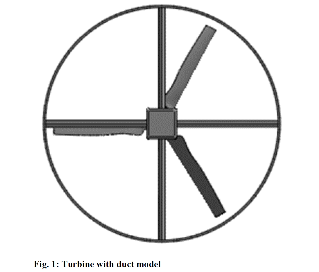
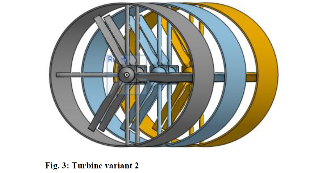
Fig. 1 shows the image of cross section view of the model. Computer Aided Design (CAD) software is used for designing the model. The model has two variants,  one is one duct with six turbines and
  one is three ducts with two turbines.
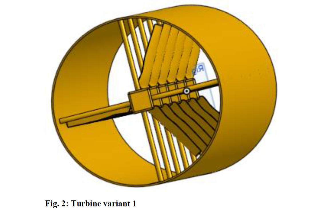
Figs. 2 and 3 shows the two variants of the model.
The turbines in a stationary system usually need some yaw and pitch mechanisms to compensate for changes in wind direction and speed. It is expected that the turbines in the moving vehicle turbine system are always oriented towards the main direction of airflow. There is an inherent mechanical advantage because there is no need to alter the blades to get the best angle of attack [3]. The air that strikes the turbine blades travels faster through the duct because of its design, which lowers drag force. The impulse force produced at the duct's sharp edges creates a drag. Therefore, the duct is constructed with a smooth surface, ignoring any sharp edges along the air entry path, in order to eliminate this impulse force [4]. High turbulence intensity and a stream-wise velocity deficit are characteristics of a wind turbine's wake. The wake deficit causes the downstream turbines to have less power available, and the high turbulence level causes the structural loads to rise, reducing the rotor blades' lifespan. Depending on how the wind farm is laid out, wake interference effects are said to cause losses in energy output of 10 to 20% [12].
3.Tip speed ratio and meshing
The speed ratio of the electric turbine helps to increase the power output and efficiency of the electric motor. If the rotor spins too slowly, no power is produced in the turbine and there is too much air in the gaps between the blades. However, if the blades spin too fast, they create too much noise and act as a solid wall against the wind. Calculating the optimal speed ratio is very important to achieve optimal efficiency. Meshing is a crucial step in the design and simulation of turbines for power generation. It involves dividing the turbine geometry into small, manageable elements or meshes to perform numerical simulations. The wind turbine edges are the most portion of the rotor. Extraction of vitality from wind depends on the plan of the edge [10]. Proper meshing is essential for accurate and reliable results in computational fluid dynamics (CFD) an alysis. Here, for our model we have used 3D tetra mesh with size of 0.1 m. To get accurate result fine mesh is needed. As said fine mesh requires more time to generate but results will be accurate. For coarse mesh generation time is less but result won’t be that much accurate. In order to apply this turbulence model and anticipate the power coefficient as well as estimate the precise power coefficient, the meshes are made with the recommended tolerance [5].
The tip speed ratio (TSR), which has a direct impact on power generation, is an essential metric in the design and operation of wind turbines. For maximum power extraction, different wind turbine designs and blade combinations have varied optimal TSR values. The blades are not effectively catching the available wind energy at low TSR values. The aerodynamic efficiency drops with very high TSR values, and the turbine may stall or produce less power. A wind turbine's power output may be decreased and mechanical stress may be placed on the turbine's components if it is operated at a TSR that is considerably off from the ideal value. For effective power generation and turbine longevity, the TSR must be kept within the ideal range. An indicator of efficiency is the power coefficient (Cp). The formula for TSR can be written as follows:

Where,
TSR - tip-speed ratio
ω - the angular velocity of the tips of the turbine rotor blades
r - radius of distribution of the tips of the turbine rotor blades
V - wind speed.
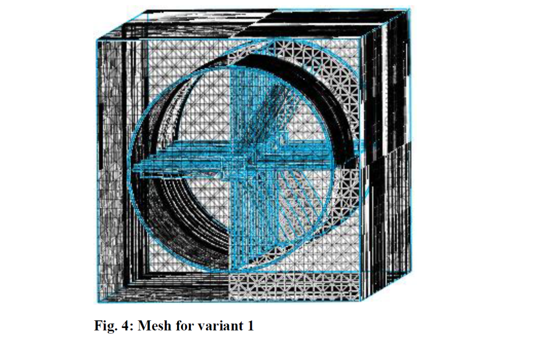
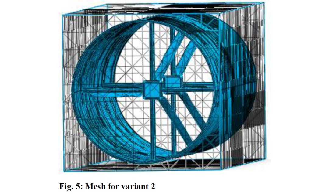
Figs. 4 and 5 show the meshed models from CFD software (midas NFX) for the variant 1 and 2 respectively. The grid was tested for convergence study and also computational accuracy, found to be conforming to the standard practices.
4.CFD inputs
Computational Fluid Dynamics (CFD) is a branch of fluid mechanics that utilizes numerical methods and algorithms to an alyze and solve problems related to fluid flow. CFD is widely used in various industries to simulate and optimize the behaviour of fluids, such as gases and liquids, in and around solid objects. Here CFD an alysis is done for the proposed model with certain inputs. CFD is carried out for the models which were mentioned in Figs. 2 and 3. Before simulation model requires certain inputs like material properties (Fig. 6)
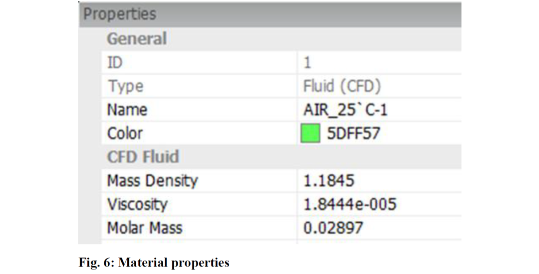
boundary conditions and loads. Our concept is to generate power through running rain using turbines, so here, Air is used as flow material and boundary conditions were set as inlet, Outlet, Wall and Velocity as shown in Fig. 7.
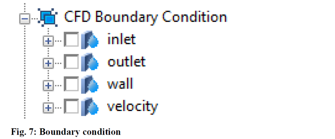
Boundary conditions are very important in CFD. This is because the effectiveness of the numerical method and the resulting quality of the software can be critically determined by the way the calculation is processed. The dynamic wake meandering, which is demonstrated to be connected to the wind turbine spacing and the vortex shedding from the turbine as a bluff body, is one of the important characteristics of wakes behind wind turbines [6]. The turbulence intensity behind the second wind turbine is found to be significantly higher than behind one unobstructed turbine. Considerably higher velocity deficits are found in the near wake behind the second turbine compared to the wake behind one unobstructed turbine [7]. An alysing CFD equations makes it simple to investigate the flow-on aerofoil geometry. In addition to being cost-effective and time-saving, it also eliminates the need for costly tests [9]. Aerodynamic drag is an important factor in the power requirements of a locomotive, as are lift resistance (gravity), frictional resistance (rolling, track, flange, bearing, suspension losses) and the force required to accelerate or decelerate. Measurements made using instrumented car and taxi methods show that aerodynamic drag can be more than 90% of the drag at higher train speeds [14].
5.Results and discussion
Results were extracted after running the model, Table 1 and 2 shows the output. The varying tip speed provides certain rpm and it results in generation of power.
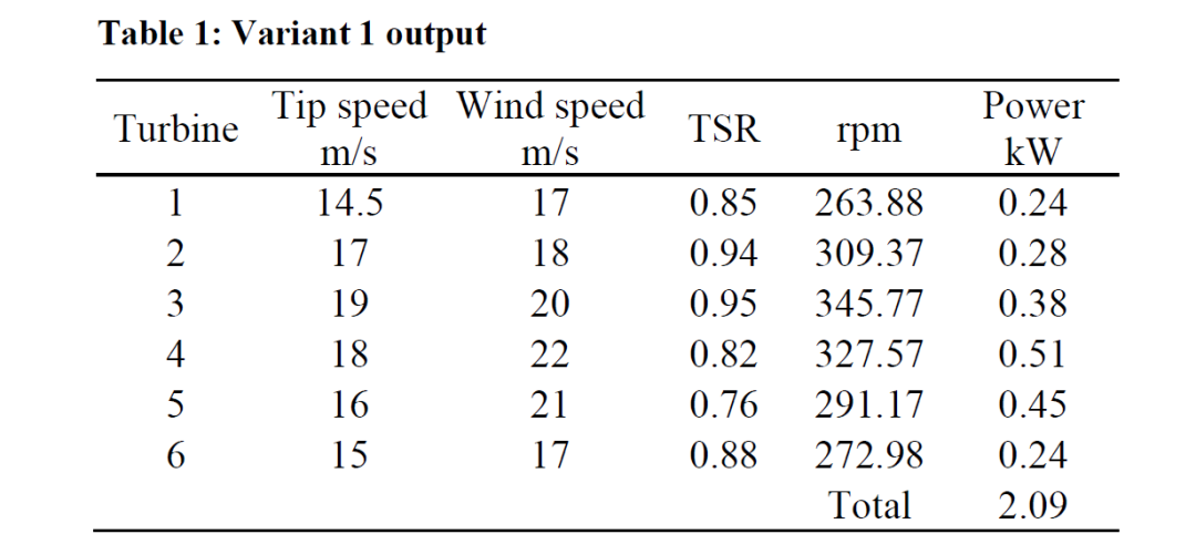
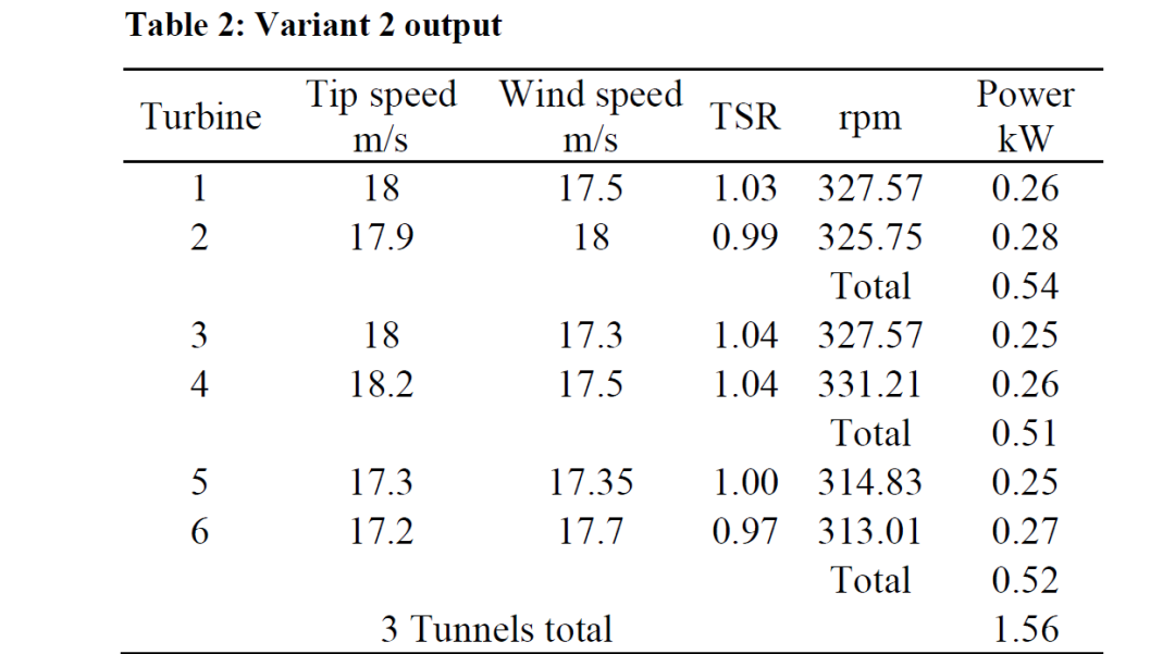
From Table 1, TSR of 0.85 produced 263.88 rpm which results in generation of 0.24 kW power. With varying TSR in all six turbines, they generated total power of 2.09 kW in the first variant. From the Table 2, TSR of 1.03 produced 327.57 rpm which results in generation of 0.26 kW power. With varying TSR in all six turbines, they generated total power of 1.56 kW in the second variant. The aerofoil's blade elemental design in a wind turbine will improve power generation efficiency. Low velocity blades travelling at less than 10 m/sec were considered for CFD design optimisation [9]. Power generation during normal times is discussed here, but when train is passing through a tunnel power generation rate may vary. The air speed will vary throughout the tunnel due to the accelerated wind flowing through it when the train passes. The train's speed and the distance from the tunnel exit of the train determine the wind speed essentially [13]. A wind turbine should be placed around a car's length from the tunnel exit, where a consistent, maximum wind speed is seen. The turbine would produce either erratic or insufficient wind flow if it were placed very close to the tunnel entrance or exit.
6.Conclusion
CFD an alysis was carried out using midas NFX for both proposed variants (models) and result shows that they produced better power than other ideas. Compared to variant 2, variant 1 produced more power, which shows prominent result. As expected this model can produce power without disturbing the performance of the train. This kind of work may help in achieving power generation through renewable resources rather than depending on non-renewable resources.
REFERENCES:
[1]S. Das, D. Mazumder, N. Mia and S. Rahman. 2020. A review on power generation from wind power created by fast moving train perspective Bangladesh, IEEE Int. Conf. Tech., Engg., Mgmnt for Societal impact using Marketing, Entrepreneurship & Talent, 1-5. https://doi.org/10.1109/TEMSMET51618.2020.9557448.
[2]M. Hyman and M.H. Ali. 2022. A novel model for wind turbines on trains, Energies, 15, 1-15. https://doi.org/10.3390/en15207629.
[3]B. Prakash, A. Rahul, D. Abhijit, D. Vikrant and P.V. Sachin. 2016. Review on wind power generation through running trains, Int. Eng. Res. J, 2, 519-523.
[4]T. Sathish, D.B. Subramanian, K. Muthukumar and S. Karthick. 2020. Design and simulation of wind turbine on rail coach for power generation, Mat. Proc., 33(7), 2535-2539. https://doi.org/10.1016/j.matpr.2019.12.033.
[5]K.M. Almohammadi, D.B. Ingham, L. Ma and M. Pourkashan. 2013. Computational fluid dynamics (CFD) mesh independency techniques for a straight blade vertical axis wind turbine, Energy, 58, 483-493. https://doi.org/10.1016/j.energy.2013.06.012.
[6]S.J. Andersen, J.N. Sorensen and R. Mikkelsen. 2013. Simulation of the inherent turbulence and wake interaction inside an infinitely long row of wind turbines, J. Turbulence, 14(4), 1-24. https://doi.org/10.1080/14685248.2013.796085.
[7]J. Bartl, F. Pierella and L. Saetran. 2012. Wake measurements behind an array of two model wind turbines, Energy Procedia, 24, 305-312. https://doi.org/10.1016/j.egypro.2012.06.113.
[8]C.D. Eleni. 2012. Evaluation of the turbulence models for the simulation of the flow over a National Advisory Committee for Aeronautics (NACA) 0012 airfoil, J. Mech. Engg. Research, 4(3). https://doi.org/10.5897/JMER11.074.
[9]M.H. Ali, S.N. Mehdi and M.T. Naik. 2021. Comparative ana lysis of low velocity vertical axis wind turbine NACA blades at different attacking angles in CFD, Materials Today: Proc., 80(3), 2091-2100. https://doi.org/10.1016/j.matpr.2021.06.119.
[10]M. Khaled. 2017. Aerodynamic design and blade angle an alysis of a small horizontal-axis wind turbine, American J. Modern Energy, 3(2) 23-37. https://doi.org/10.11648/j.ajme.20170302.12.
[11]J.U. Parakkal, K.E. Kadi, A.E. Sinawi, S. Elagroudy and I. Janajreh. 2019. Numerical a nalysis of VAWT wind turbines: Joukowski vs classical NACA rotor's blades, Energy Procedia, 158, 1194-1201. https://doi.org/10.1016/j.egypro.2019.01.306.
[12]S. Sarmast, H.S. Chivaee, S. Ivanell and R.F. Mikkelsen. Numerical investigation of the wake interaction between two model wind turbines with span-wise offset, J. Physics: Conf. Series, 524(1), 1-10. https://doi.org/10.1088/1742-6596/524/1/012137.
[13]R. Rangappa, S. Vathumalai and E. Chung. 2015. CFD ana lysis on wind flow characteristics while a train passing through the tunnel, Int. J. Advances in Mech. and Civil Engg., 2(3), 51-54.
[14]J.C. Paul, R.W. Johnson and R.G. Yates. Application of CFD to rail car and locomotive aerodynamics, The Aerodynamics of Heavy Vehicles II: Trucks, Buses, and Trains, 41, 259-257.
author

From

doi: 10.4273/ijvss.16.2.26