Deform-3D Machining(turning) Lab切削模拟

摘要:
本文为 DEFORM-3D 车削切削仿真实操教程,介绍专用加工向导的完整建模流程。仿真以 AISI 1045 钢工件、TNMA33 刀片与 DTGNL 刀杆为研究对象,设定切削速度、进给量、背吃刀量等工艺参数。依次完成单位选取、刀具与刀杆调用、网格划分、边界及材料设置,选用 Usui 模型定义刀具磨损参数。软件可模拟切削力、温度、切屑形态与刀具磨损,支持瞬态与稳态分析。文档附带刀具、刀杆库参数及单位换算表,步骤清晰,可指导工程人员完成三维车削仿真,也适用于镗、钻等同类切削工艺建模。
3D MACHINING(TURNING)LAB
1)System summary 2
2)Starting the 3D machining wizard 4
3)Process setup and conditions 5
4)Insert definition 6
5)Tool Holder definition 7
6)Insert mesh and boundary conditions 8
7)Work piece geometry and mesh generation 9
8)Simulation controls and tool wear definitions 11
9)Running the simulation 12
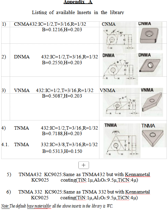
Appendix A List of available library inserts 13
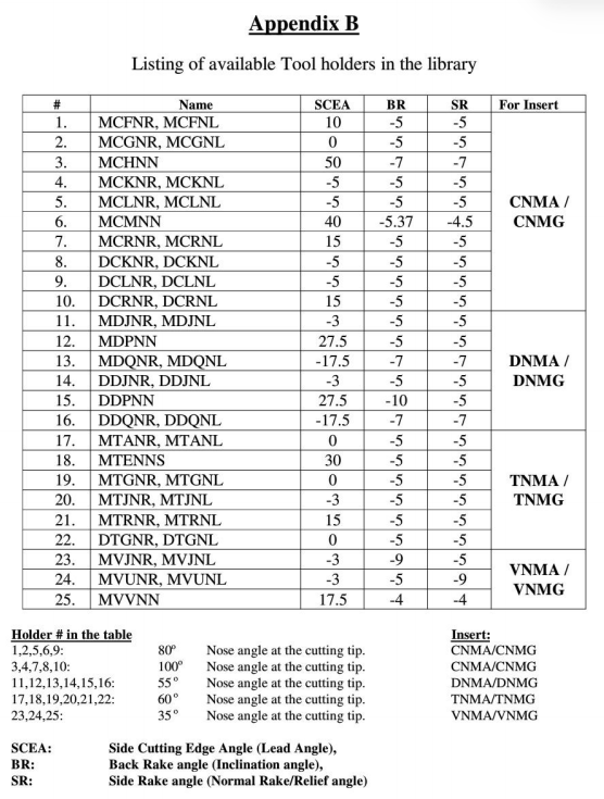
Appendix B List of available library tool holders 14
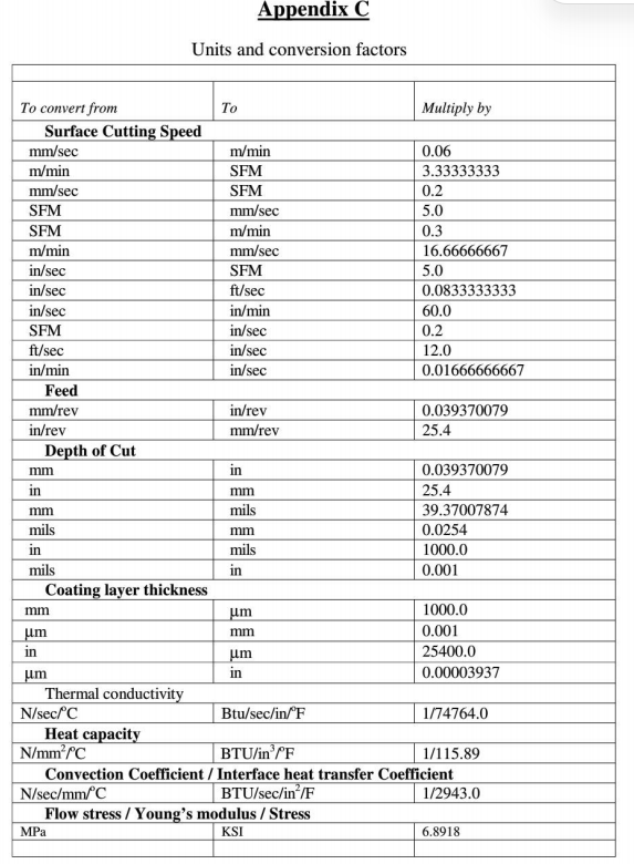
Appendix C Units and conversion factors 15
1)System summary
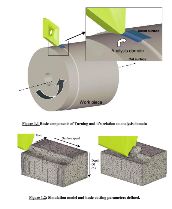
This document details the current modeling capabilities available in DEFORM3DTMsystem to simulate 3D metal cutting environment in turning process.The system can be used to model the industrial turning process,without any assumptions that are associated with orthogonal cutting conditions.These modeling procedures enable the engineer to study the process response for any change in process conditions.Cutting forces,cutting temperatures,chip shape,tool wear and tool life computations can be performed using this system.The engineer can study the effect of process parameters like, cutting speed,feed rate and depth of cut on the process response.DEFORM3DTM supports a special purpose template that simplifies the model definition and uses the same engineering language of process engineer.For turning applications the rotating work piece,insert and their relation to the an alysis domain are shown in Figure 1.1.Typical an alysis model generated using the current system is shown in Figure 1.2.The main data requirements to model the machining process are material flow stress data for the work piece material and geometric data for the insert.The material flow stress data should cover the strain rate,strain and temperature range for metal cutting process.For most materials the typical range for strain rate is 0-~10⁶/sec,the range for strain is 0-5 and the range for temperature is 20-1200℃.Special material characterizing techniques are required to address this range of loading conditions.The insert geometry can be made available in STL form,generated from any CAD system.
This lab explains the step by step procedure of building the model.This includes specifying the process data,loading the materials,inserts and tool holders from the library. By specifying the model specific data,user can generate complete data required for the a nalysis.This stage of an alysis constitutes the initial transient an alysis.After executing the simulation and sufficient chip has formed,user can compute the steady state response of the process which includes the prediction of steady state thermal response and chip geometry.From the viewpoint of insert thermal response this stage will significantly reduce the computing time that is normally associated with transient a nalysis.The results obtained from this stage form important input to the tool wear and tool life computations. The machining template comes with a set of library files for the insert geometry.User can also use any other insert geometry and save it along with the system library for any subsequent use.The list of appendix information is provided to indicate the currently available insert and tool holder data.
2)Starting the 3D machining wizard
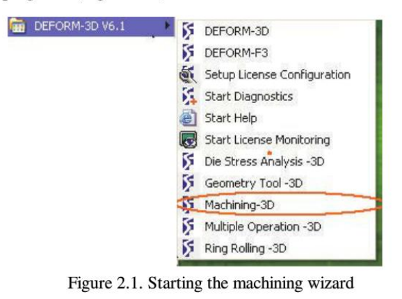
Machining wizard can be opened as a stand alone module (or the complete system)or as a special preprocessor to setup the machining problem.When opened as a stand alone module user can not only setup the problem,but also add additional operations to carryout steady state,and tool stress computations apart from access to special post processor. When opened from the regular GUI main menu either as a new problem or opening the existing problem user can access the preprocessor part of the system.On PC user can open the complete system by clicking on “All Programs”and click on this module from the list of installed programs.(Figure.2.1)
On Unix/Linux systems this stand alone machining module can be started thru an alias (3d_cutting' is the alias name) at the command prompt. (for example '/home/user/joe/3d_cutting')Installation procedures ensure that the correct alias definition is setup.
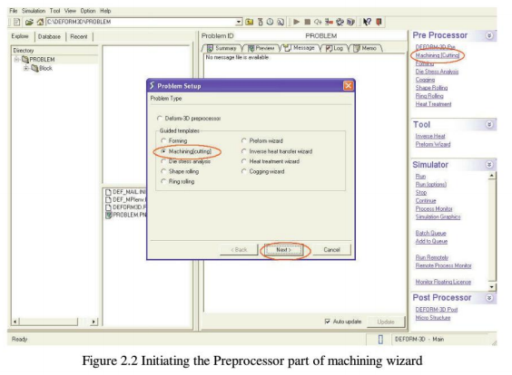
Opening the preprocessor part of the machining wizard from the GUI main menu is indicated in Figure 2.2.Here user has options to start a new session,or open an existing session.This part of the system has same access procedures on both PC and Unix/Linux.
In this lab we go through a typical setup with process conditions as follows
● Material used:AISI 1045 Steel,Initial temperature=20℃.
● Insert used:TNMA332(uncoated,WC as base material),Tool holder:DTGNL
● Process:Cutting speed=250 mm/sec,Feed=0.35 mm/rev,Depth of cut=0.3 mm
3)Process setup and conditions
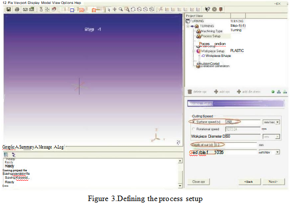
After opening the wizard,specify the unit system as ‘SI’,indicate the problem/project name and the process type as "Turning'.For each of these steps and for the reminder of this document clicking on 'Next’will navigate through the subsequent steps unless otherwise stated.Boring and Drilling are the other process types for which this wizard can be used to setup the process model.Process conditions for tuning can now be defined as 250 mm/sec for cutting surface speed,0.3 mm for depth of cut and 0.35 mm/rev for feed rate.In the subsequent ‘Process conditions'menu,define 20℃ as environment temperature,0.5 as shear friction factor and 45.0 N/Sec/mm/C as interface heat transfer coefficient.
4)Insert definition
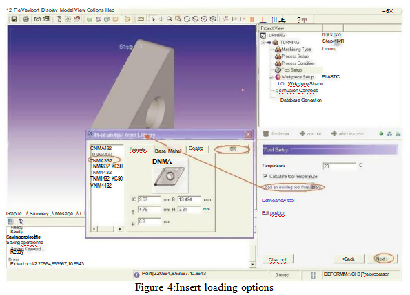
In the ‘Tool Setup’menu,select the first option 'Load an existing tool from library' (Figure 4)to load the required insert(TNMA332)from the library.Once the insert is identified user can check the basic parameters of this insert,base material details and coatings if any,prior to loading the same.
5)Tool Holder definition
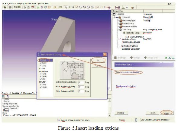
For the selected insert,the corresponding tool holders can be loaded from the tool holder library,or a new tool holder can be defined by providing basic cutting angles.Any new tool holder user creates can be saved in the library and accessed for subsequent modeling sessions.For the insert TMNA332,the wizard will indicate the available holders from the library.Load the holder DTGNL from the library(Figure 5).Basic cutting angles that are inherited from the tool holder data are SCEA(side cutting edge angle or the lead angle), BR(back rake angle)and SR(side rake angle).These basics angles and the process data (feed rate and depth of cut)control the correct position of the insert with respect to the work piece.User can also define different cutting angles for a new holder and save them in the library for later use.
6)Insert mesh and boundary conditions
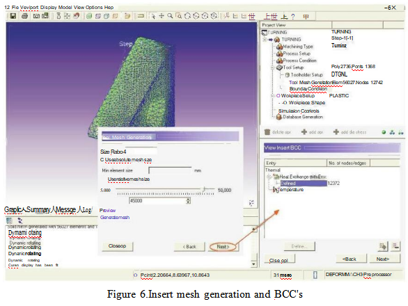
In the ‘Tool Mesh Generation'menu select the size ratio as 4,and using 45000 tetrahedral elements generate mesh for the insert.Cutting edge information being part of the insert data,the wizard automatically applies finer mesh near the cutting zone.After this stage (click 'Next')check on the thermal boundary conditions the system applies on the insert mesh.The surface far from the rake surface are applied with specified temperature and rest of the faces are applied with heat exchange with environment boundary conditions. (Figure 6).In the next menu for work piece setup select Plastic'for work piece object type.Click 'Next'to continue.
7)Work piece geometry and mesh generation
In the ‘Workpiece Shape'menu,specify the work piece details.Depending upon the work piece diameter user can specify either a flat model or a curved model.The template will prompt for the related data,and will generate the work piece setup in the display area.For the current lab we use a 'simplified model’with 7 mm length and first click on ‘Create geometry'and then 'Next'to continue.
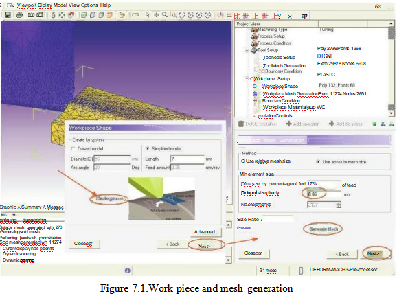
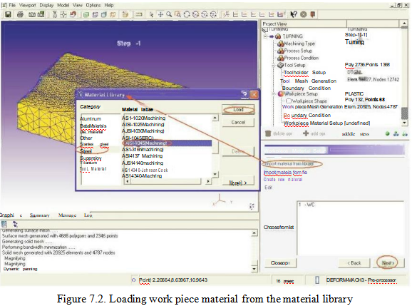
After the work piece geometry is generated,generate mesh with element size ratio of 7, and minimum element size of 0.06mm.(Figure 7.1)Click on 'Generate Mesh'to generate mesh and 'Next'to continue.In the next step load the work piece material from the library.For this example we load ‘AISI 1045(machining)’from steel category.(Figure 7.2).Click 'Next'to continue.
8) Simulation controls and tool wear definitions
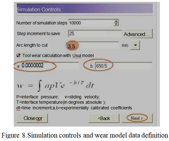
Specify the simulation controls, including the number of steps (10000), steps to save (25) and length of cut (3.5mm) for the initial Lagrangian run. Even though we have specified large number of steps, simulation will have a stopping criteria based on length of cut. Then check on the tool wear model parameters. Currently the system supports only 'Usui's' model. The coefficients used in this model should be determined based on experimental calibration as they depend on the process conditions and the materials used for accurate results. As an example for this case we use a = 0.0000002 and b = 650.5 (Figure 8).
After this user can ‘Generate the database'and 'Close'this operation to run the simulation
9)Running the simulation
After closing the operation,click on the 'Simulator'and on ‘Run simulation’(Figure 9)to start the simulation.
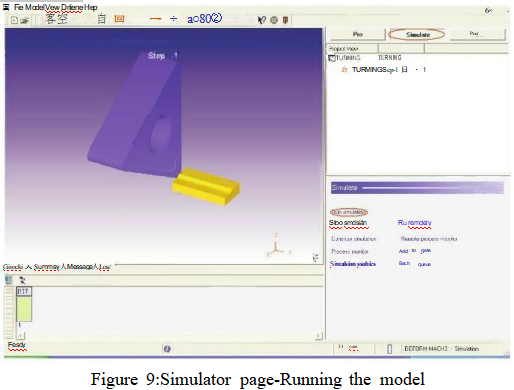
After completing the simulation,user can either review the results by selecting ‘Post'or proceed to setup the data required for steady state run or tool stress simulation.
免责声明:
本页面/内容部分素材来源于互联网公 开 信 息,旨在传递更多信息,不代表本平台立场。
版权归原作者或机构所有,如涉及侵权,请通过平台联系我们,我们将在核实后第一时间处理。
本平台对转载内容的真实性、准确性不作任何保证,用户需自行判断并承担使用风险。