烃类燃料氧化动力学机理与模拟研究

烃类燃料氧化动力学机理与模拟研究(on_the_kinetics_of_hydrocarbons_oxidation_from_natural_gas_to_kerosene_and_diesel_fuel)
摘要:
本文系统研究从天然气到煤油、柴油的烃类燃料氧化动力学,采用激波管、搅拌射流反应器与层流火焰实验,构建层级式详细化学反应机理。以甲烷、乙烷、丙烷等小分子组分构建天然气模型;以正癸烷、丙基环己烷、丙基苯替代煤油;以正十六烷、异辛烷等模拟柴油。机理覆盖烷烃、环烷烃、芳烃氧化路径,经组分浓度、点火延迟、火焰速度验证,能较好预测天然气与煤油氧化行为,柴油模拟因缺少多环芳烃机理仍需完善。研究明确关键基元反应与灵敏度,为工程燃料燃烧模拟提供模型与机理支撑。
Kinetic reaction mechanis ms are necessary for modeling the combustion, oxidation and ignition of commercial fuels consisting of complex mixtures of hydrocarbons. Since they are generally too complex to be considered in the models directly, simple model-fuels are preferred. These model-fuels consist in a simple mixture of hydrocarbons for which kinetic oxidation models are validated. The oxidation of a large variety of hydrocarbons was studied experimentally in a jet-stirred reactor to build the needed kinetic reaction
mechanis ms. These detailed kinetic reaction mechanis ms were assembled to model the oxidation of commercial fuels. The capabilities of these kinetic models to simulate the oxidation of natural gas, kerosene and gas oil are presented together with needs for new kinetic measurements.
Introduction
Practical fuels such as natural gas, gasoline, kerosene, gas oil (diesel fuel) are complex mixtures of hydrocarbons. In order to improve the combustion of these fuels while reducing the formation of pollutants, it is necessary to propose and validate kinetic reaction mechanis ms in simple and well-defined labora- tory conditions (i.e. plug-flow reactors, jet-stirred reactors, shock-tubes, premixed flames) for the combustion of selected simple hydrocarbons representing the major components of practical fuels. A practical fuel will then be represented in the model by a simple mixture of hydrocarbons called the model-fuel. Results obtained for the kinetic modeling of the oxidation of practical fuels using simple model-fuels are pre- sented. They rely on experimental results obtained in this laboratory using jet-stirred reactors and shock-tubes and on experimental results taken from the literature (ignition delays, flame speeds, flame structures)
Experimental set-up used to obtain mode validation data
The kinetic reaction mechanis ms were primarily developed based on experimental data obtained in a jet-stirred reactor (JSR). The JSR experiment used was described earlier.1,2 The reactor consisted of a 40 mm diameter sphere made of fused silica (to prevent wall catalytic reactions) equipped with 4 noz- zles of 1 mm id for the admission of the gases which are achiev- ing the stirring. A nitrogen flow of typically 100 L h__1 was used to dilute the fuel. All the gases were preheated before injection, minimizing temperature gradients inside the JSR. A regulated heating wire of ~1.5 kW maintained the tempera- ture of the reactor at the desired working temperature. The reactants were diluted by nitrogen (<50 ppm of O2 and H2O; <1000 ppm of Ar; <5 ppm of H2), and mixed at the entrance of the injectors.1 High purity reactants were used in the experiments: oxygen was 99.995% pure and the neat hydro- carbons were >99% pure. Furthermore, when liquid fuels were studied, they were thoroughly sonically degassed before use. A piston pump or an HPLC pump was used to deliver the liquid fuel to an atomizer–vaporizer assembly maintained at 100–250 oC, depending on the boiling point of the fuel. The reacting mixtures were probe-sampled by means of a low-pressure sonic quartz probe. The samples (≤30 Torr 三 4 kPa) were taken at steady temperature and residence time. They were an alyzed on-line by means of a GC-MS, and off- line, after collection in 1L Pyrex bulbs: low vapor-pressure che- micals were an alyzed on-line whereas high vapor-pressure compounds and permanent gases were an alyzed off-line. In the experiments involving nitric oxide, a FTIR spectrometer was used for on-line an alyses. The experiments were performed at steady state, mostly at a constant mean residence time, t, the reactants flowing continually in the reactor, varying stepwise the temperature of the gases inside the JSR. A high degree of dilution was used (0.07–0.9% vol. of fuel), reducing tem- perature gradients in the JSR and heat release (no flame occurred in the JSR).
Several gas chromatographs (GC), equipped with capillary columns (Poraplot U, Molecular Sieve 5A, DB5ms, DB624, Plot Al2O3/KCl, Carboplot P7), thermal conductivity detector (TCD) and flame ionization detector (FID), were used for the measurement of stable species. Compounds identifications were made through GC/MS an alyses of the samples. An ion trap detector operating in electron impact ionization mode (GC/MS Varian Saturn) was used. CH2O and CO2 were mea- sured by FID after hydrogenation on a Pt/H2 catalyst con- nected to the exit of the GC column. A good repeatability of the measurements and a good carbon balance (±10%) were generally obtained.
Kinetic modeling
The chemical kinetic modeling of the JSR experiments was performed using the PSR computer code3 that calculates spe- cies concentrations from the balance between the net rate of production of each species by chemical reaction and the differ- ence between the input and output flow rates of species. These rates were computed from the kinetic reaction mechanis m and the rate constants of the elementary reactions calculated at the experimental temperature, using the modified Arrhenius equa- tion: k = A × Tb × exp(__E/RT).
The ignition delays were computed, using the Senkin computer program, assuming the validity of the constant volume approximation under reflected shock wave conditions.
The fuel-air burning velocities at 298 K, Su , were computed using the Premix computer package.5 Care was taken in the calculations to reach the final solution (no evolution of Su when the number of mesh points is increased); typically > 100 points were computed.
The kinetic scheme used here is based on the comprehensive mechanis m developed for the reduction of NO by natural gas blends in simulated reburning conditions using a natural gas blend,6 methane, ethane, ethylene, acetylene, propane, pro- pene, n-butane and isobutane7–15 and the oxidation of 1,3-butadiene,16 benzene,17 toluene,18 n-propylbenzene,19 cyclohexane and n-propylcyclohexane.2,20 The reaction mecha- nis m has a strong hierarchical structure; it is available from the author. The rate constants for reverse reactions were computed from forward rate constants and the appropriate equilibrium constants, Kc = kforward/kreverse , calculated using thermoche- mical data.21–23 The pressure dependencies of unimolecular reactions and of some pressure-dependent bimolecular reac- tions were taken into account when information was available (i.e., k(P, T)). In the course of the model development, first- order local sensitivity an alyses, Si,j = ∂ln(mole fraction of i)/ ∂ln(kj), were performed as well as reaction rates an alyses by computation of rates of consumption and rates of production for every species.
The oxidation and combustion of natural gas
Natural gas (NG) is a major and the simplest fuel widely used on earth. Its composition varies from one source to another (see Table 1). Nevertheless, methane, ethane and propane are the main hydrocarbon constituents of NG. To sustain and enhance the competitiveness of NG use in the production of energy and forecast the effects of changes in composition, we need to pro- vide engineers with predictable tools allowing the design of still higher performance burners. Among these tools, predictive kinetic reaction mechanis ms are needed. Such mechanis ms have been proposed based on methane oxidation, ignition and com- bustion data, mostly. Very few used data obtained for the oxidation, ignition and combustion of NG. Tan et al.24,25 pro- posed such a mechanis m that was further used and tested26–28 for the ignition, oxidation and combustion of natural gas. This natural gas kinetic reaction mechanis m was validated against JSR experimental results, consisting of mole fraction profiles of reactants and products, obtained in a wide range of condi- tions (1–10 atm, from fuel lean to fuel-rich conditions, 800– 1400 K, and variable residence time). Fig. 1 presents a compar- ison between the experimental data and the kinetic modeling for the oxidation of methane, a methane–ethane mixture, a methane–ethane–propane mixture and a standard NG oxidized in the same experimental conditions. These results clearly show that NG oxidizes easier than methane and that the methane– ethane–propane mixture is the best model-fuel to be used in these conditions. More details can be found in previous papers.24,25 Sensitivity an alyses indicated that in the JSR con- ditions, the most sensitive reactions are:
H + O2 → OH + O
H + O2 + M → HO2 + M HO2 + OH → H2 O + O2
HCO + M → H + CO + M
CH4 (+M) → CH3 + H(+M)
CH3 + HO2 → CH3 O + OH
2CH3 (+M) → C2 H6 (+M)
CH3 + O2 → CH3 O + O
CH3 + O2 → CH2 O + OH
The proposed kinetic model was also used to simulate the igni- tion of various methane and NG blend mixtures24,25 and the methane–air flame speeds.24 Fig. 2 provides a comparison between our recent modeling and that obtained using the GRI 3.0 mechanis m.29 As can be seen from this figure the models are in close agreement with the data.
The burning velocities were mostly sensitive to the kinetics of:
H + O2 → OH + O
H + O2 + M → HO2 + M
CO + OH → CO2 + H
HCO + M → H + CO + M
CH3 + H(+M) → CH4 (+M)
Further validation of the proposed kinetic scheme were obtained for the interaction of NO with C1 to C4 hydrocarbons and natural gas blends.6,7 Figs. 3–5 present a comparison between our modeling and the JSR data obtained by Chen and Malte and at CNRS for the reduction of NO by methane, a methane–ethane mixture, and ethane. Again, the agreement between the data and the modeling is good, supporting the kinetic scheme used. However it was demonstrated7 that the GRI 3.0 mechanis m29 could not represent all these data due to missing reactions in the NOx sub-mechanis m. Our NG kinetic reaction mechanis m was used as a C0–C6 base set for the modeling of the oxidation of the more complex practical fuels considered here. These studies showed that the kinetics of the reactions producing and consuming HCCO was critical. Also, the kinetics of vinyl decomposition is very influential. Unfortunately, there is a lack of kinetic data for this reaction particularly concerning its pressure and temperatures depen- dencies.
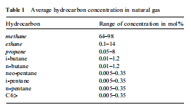
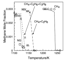
Fig. 1 The oxidation of methane and mixtures with higher alkanes in a JSR at 1 atm and a residence time of 0. 14 s. A: CH4 0.3%, O21.2%; B: CH4 0.3%, O2 1.2%, C2H6 0.03%; C: CH4 0.3%, O2 1.2%, C3H8 0.03%; D: CH4 0.3%, O21.2%, C2H6 0.03%, C3H8 0.0046%; E: CH4 0.3%,O21.2%, C2H6 0.033%, C3H8 0.0063%, n-C4H10 0.00024%, iso- C4H10 0.00031%, n-C5H12 0.00017%, iso-C5H12 0.00017%, n-C6H14 0.00017%). The symbols represent experimental data while the lines are the computed results.

Fig. 2 Methane–air flame speeds at 1 atm and 298 K. Our modeling is compared with the predictions of the GRI 3.0 mechanis m and the available data (AB72: ref. 30; AB73: ref. 31; GJ72: ref. 32; R71: ref. 33; L68: ref. 34; DL98: ref. 35).

Fig. 3 The reduction of NO by methane in a JSR at 1580 K, t = 9 ms, 5000 ppm of NO.36 The data (symbols) are compared to our mod- eling (lines).

Fig. 4 The reduction of NO by methane in a JSR at 1800 K, t = 9 ms, 5000 ppm of NO.36 The data (symbols) are compared to our mod- eling (lines).

Fig. 5 The reduction of NO by a NG blend (CH4/C2H6 10 : 1 mix- ture) at 1 atm (1350 K; t = 0. 12 s; 1000 ppm of NO; 7272 ppm of CH4 ; 728 ppm ofC2H6 ; [TFN] = [NO] + [HCN]). The data (symbols) are compared to our modeling (lines).

Fig. 6 GC/MS an alysis of a kerosene TR0 sample showing the importance of n-alkanes.
oxidation rates in JSR37–39 and in flame conditions.40 Fig. 7 presents a comparison between JSR results obtained for the oxidation of kerosene and n-decane at 10 atm. It clearly shows that n-decane is an acceptable model fuel for modeling kero-sene oxidation if the formation of aromatics is not a major issue. However, more complex model fuels are necessary to model the formation of aromatics from the oxidation of kero- sene. The use of surrogates consisting of binary mixtures of n- decane and toluene or n-propyl benzene showed that the level of aromatics was difficult to simulate in JSR conditions.41,42 A much better agreement between the experimental results and the modeling can be obtained using a mixture of n-decane, n-propylbenzene and n-propylcyclohexane, as presented here. This results from the important reactions of the cycloalkane fraction of the fuel. The detailed kinetic reaction mechanis ms for these pure compounds had first to be established before merging the sub-mechanis ms to yield a kerosene kinetic reac- tion mechanis m.

Fig. 7 Comparison between JSR experimental results obtained for the oxidation of kerosene (large symbols), n-decane (s maller symbols and interpolation line) and the modeling using n-decane as model-fuel (s mall symbols and spline line). The initial conditions were: 0. 1% of fuel, residence time = 0.5 s, 10 atm).
The oxidation of n-decane
The oxidation of n-decane was studied in a JSR over a wide range of experimental conditions (1–40 atm, 500–1400 K, equivalence ratio φ = 0.2 to 2). Most of the data have been reported in the literature.37–39,41,42 The kinetics reaction sub- mechanis m was built based on general scheme: initiation by thermal decomposition and reaction with O2 , propagation via H-atom abstraction by s mall radicals (see Table 2), radical decomposition, isomerization and reaction with O2 . Fig. 8 pre- sents a comparison of the experimental results obtained for the oxidation of n-decane at 1 atm in fuel-rich conditions. As can be seen from this figure the model is in very good agreement with the data and can be used as a subset of a kerosene detailed kinetic reaction mechanis m. The sensitivity an alyses indicated that besides the reactions of the C0–C1 sub-mechanis m, the reactions of the fuel with H, O, OH and HO2 are sensitive.
The oxidation of simple cycloalkanes
So far, the oxidation of cycloalkanes in the high temperature regime was only studied in JSR conditions.2,20,43 The results of these studies were used to propose a kinetic scheme for the oxidation of cyclohexane and n-propylcyclohexane.
1. Cyclohexane. A detailed kinetic reaction mechanis m was recently proposed for the oxidation of cyclohexane,20 improv- ing a former mechanis m2 that over-predicted the formation of cyclohexene and 1,3-cyclohexadiene. The initiation reactions for the oxidation of cyclohexane included C–C and C–H bond cleavage. The cyclohexyl (cy-C6H11) chemistry was detailed: The isomerization of cyclohexyl, yielding linear C6H11-16 (5-hexenyl) was not explicitly included previously.2
cy-C6 H11 → C6 H11 -16
This radical isomerizes yielding 1-hexen-3-yl (C6H11-13) and 1-hexen-2-yl (C6H11-12).
C6 H11 -16 → C6 H11 -13
C6 H11 -16 → C6 H11 -12
1-Hexen-2-yl isomerizes yielding 1-hexen-5-yl.
C6 H11 -12 → C6 H11 -15
5-Hexenyl decomposes, yielding 3-butenyl and ethylene,
C6 H11 -16 → 3-C4 H7 + C2 H4 and 1-propyl and allene.
C6 H11 -12 → nC3 H7 + aC3 H4
The decomposition of 1-hexen-5-yl yields allyl and propene; that of 1-hexen-3-yl forms ethyl and 1,3-butadiene and also 1,3-pentadiene and methyl.
C6 H11 -15 → aC3 H5 + C3 H6
C6 H11 -13 → C2 H5 + C4 H6
C6 H11 -13 → C5 H8 -13 + CH3
The kinetics for the above isomerizations and decompositions were estimated by an alogy with similar reactions for which kinetics had already been established. The inclusion of these reactions improved the modeling of cyclohexane avoiding the over-prediction of cyclohexene and cyclohexadiene at low fuel- conversion. Again, kinetic data are missing for important reac- tions in this submechanis m. This is particularly the case for the reactions of decomposition of the fuel and of its primary radi- cals produced by methatesis. Fig. 9 presents a comparison between the JSR data and the modeling. As can be seen form this figure, the oxidation of cyclohexane in a JSR is well-pre- dicted by the proposed model.
详细内容请见附件
免责声明:
本页面/内容部分素材来源于互联网公 开 信 息,旨在传递更多信息,不代表本平台立场。
版权归原作者或机构所有,如涉及侵权,请通过平台联系我们,我们将在核实后第一时间处理。
本平台对转载内容的真实性、准确性不作任何保证,用户需自行判断并承担使用风险。