ANSYS13.0中更新的 AQWA 与 ASAS 产品 (英文讲义)

摘要:
这份文档是 ANSYS 13.0 版本中AQWA 与 ASAS 两款海洋工程专用模块的更新介绍讲义。内容先概述 AQWA 专注海洋结构水动力分析,支持频域 / 时域、多体耦合、系泊与缆索动力学;ASAS 面向海洋平台全局结构有限元分析与疲劳校核。13.0 版重点实现 AQWA 全面接入 Workbench,新增水动力时域响应系统,强化缆索弯曲刚度、非线性轴向刚度与自定义刚度矩阵。ASAS 技术迁移至 Mechanical,优化梁单元、波浪理论与土 - 桩 - 结构耦合,并新增 Design Assess ment 设计评估系统,提供 FATJACK、BEAMCHECK 等专用校核工具。整体完成水动力与结构仿真深度集成,提升海洋工程全流程仿真能力。
AQWA & ASAS Product Updates for ANSYS 13.0
Contents
• AQWA & ASAS Overview
– Products and Applications Areas
– Product Roadmap
• Release 13.0 Update
• Outlook
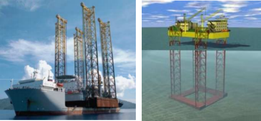
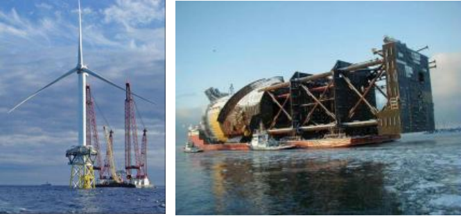
Offshore Structures
– Fixed
• Steel Jackets
• Concrete
– Compliant
• Jack-ups
– Floating
• FPSOs
• SPARS
• Semi-Submersibles
• Tension Leg Platforms
– Risers
– Offshore Wind Turbines
• Harbours
• Ships
– Design
– Offloading
Offshore Products- How they fit with ANSYS portfolio
General Products:
• Design Modeler
• ANSYS Mechanical
• CFX/FLUENT
Vertical Applications:
• AQWA
• ASAS
Offshore Products - AQWA
• Comprehensive Hydrodynamic capabilities
– Diffraction/Radiation including Morison elements
– Frequency Domain an alysis
– Stability including mooring lines
– Time domain with irregular waves
– Time domain with non-linear survival waves
– Coupled Cable Dynamics
– Multiple hydrodynamic interaction and articulations (up to 50 structures)
– Transfer of motions and Pressures to ASAS & ANSYS FE models
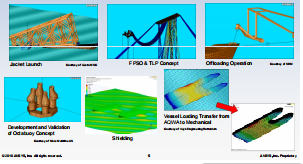
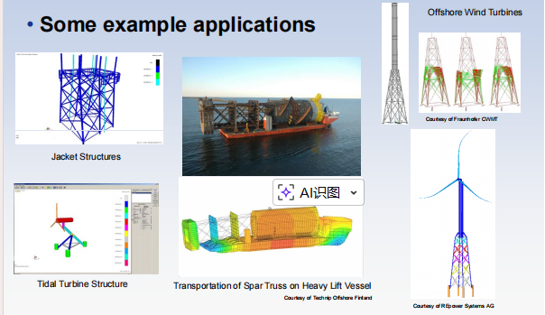
AQWA- Typical Applications
• Some example applications
Offshore Products - ASAS
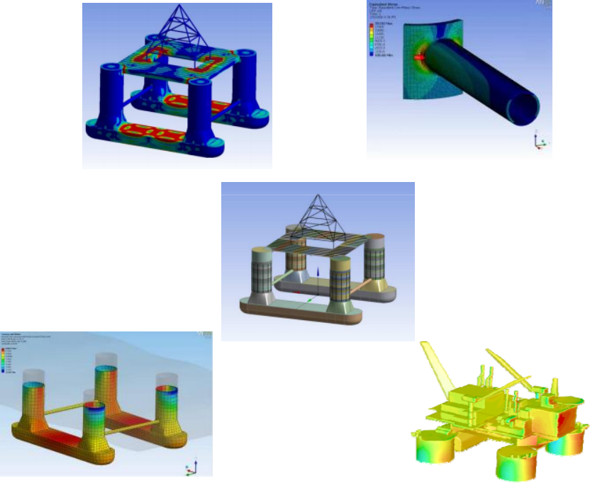
• FE based offshore structural an alysis suite
– Mainly used in “global” design ana lysis
– Unique post-ana lysis assess ment tools specific to offshore requirements
• Some key features
– Coupled wave-structure interaction with regular/irregular waves
– Coupled hydro-elastic ana lysis for tubular framed structures
– Wave loading and added mass for jackets and similar structures
Spectral and deterministic faftgue of jackets
– Toolkit to facilitate user software integration
ASAS- Typical Applications
• Some example applications
Product Roadmap - AQWA
• Migration of AQWA to Workbench
– AQWA unique in ANSYS
– Provides parameterization and interfacing/coupling
with other tools/products (geometry, meshing, solvers)
Product Roadmap - ASAS
• Transfer of ASAS unique solver technology to ANSYS Structural Mechanics products
– Never any long term scope for developing/supporting multiple FE products
– Recognition of ASAS key features
• Creation of a Design Assess ment system to handle post-processing of an alysis results
– For offshore, this covers load case combinations and code checking
• Additional Products
– Separate Code Checking and Fatigue Products
Offshore Products at R13 - Feature Summary
• AQWA
– AQWA in Workbench
– AQWA Core Developments
• ASAS to Mechanical
– Beam Modeling
– Wave theories
– Soil-Pile-Structure Interaction
• Design Assess ment
– New Design Assess ment system in Mechanical
– Additional code checking products
AQWA in Workbench- Hydrodynamic Diffraction System
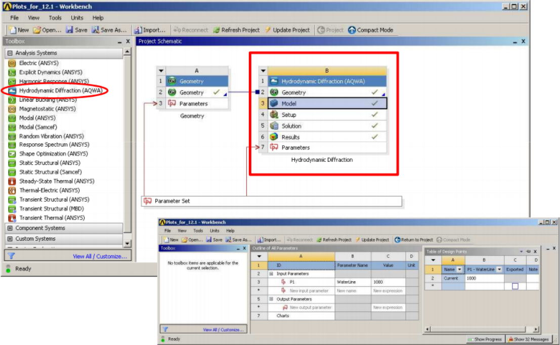
AQWA in Workbench - Hydrodynamic Diffraction System
• Initial implementation at 12.1
Extended to cover most of AQWA Diffraction product
– AQWA LINE now fully reproduced in the HD system (including recent
core enhancement enabling mooring line representation)
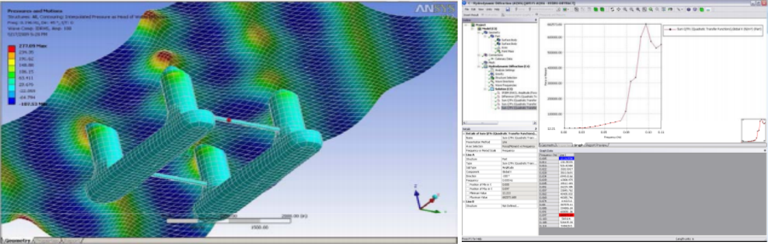
– New QTF and SF/BM Graphs
– AQWA WAVE capabilities to
transfer pressures etc to
Mechanical not implemented in
WB – but the capability does exist and is documented
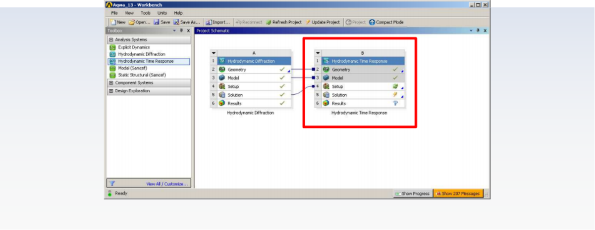
AQWA in Workbench - Hydrodynamic Time Response System
• New Hydrodynamic Time Response An alysis System
– Time history an alysis of bodies, subject to environmental forces including mooring lines
AQWA in Workbench - Hydrodynamic Time Response System
• Input for the following completed:
– Cable connections for rigid body motion, wave and mooring line a nalysis under various ocean
environments
– Ocean Environment Definition
for Wind, Wave and Current
– Additional Structure Force Time History
– Cable Winching and Failures
– Input of catenary mooring lines
– Realistic viewing of mooring lines
– Graphing of various results
• Displacement, velocity, acceleration
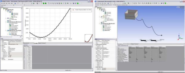
AQWA in Workbench - Hydrodynamic Time Response System
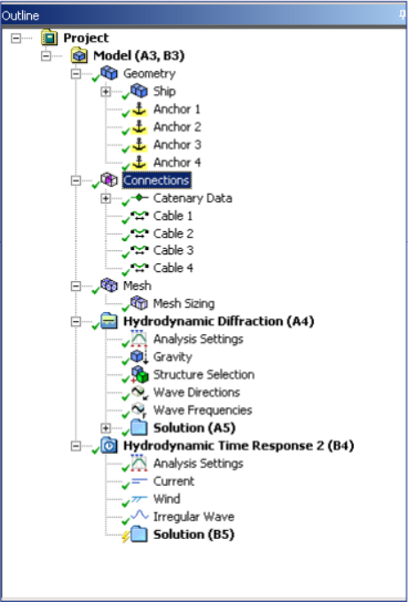
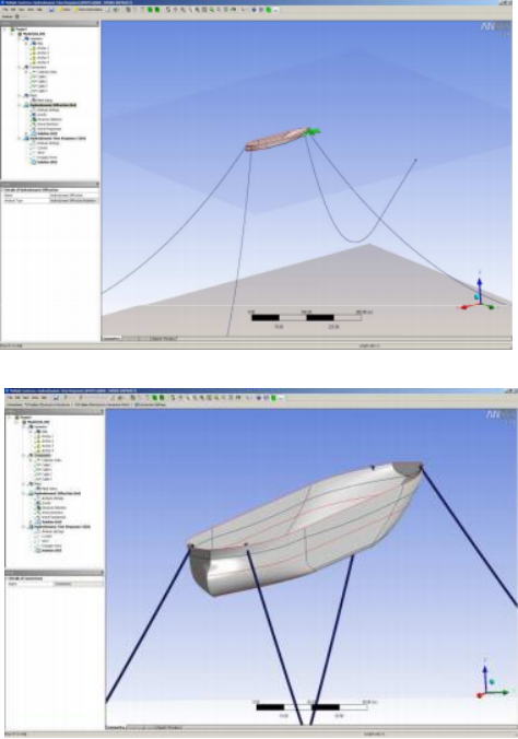
AQWA Core Developments
• Cable Dynamics
– Bending stiffness allows modeling of rigid and flexible
risers (previously only rigid risers could be modeled using tethers)
– Non-linear axial stiffness to enable more rigorous modeling of synthetic moorings. Uses polynomial definition of tension v extension.
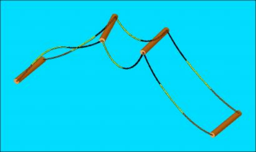
AQWA Core Developments
• User-defined stiffness matrix connecting separate ships
– This enables mooring system to be included in diffraction/radiation ana lysis
• Response spectra available for any specified position on ship (previously limited to CoG)
• Response spectra available for intermediate
positions (connection points) along mooring lines
• ISO wind spectrum definition added for dynamic motions ana lysis
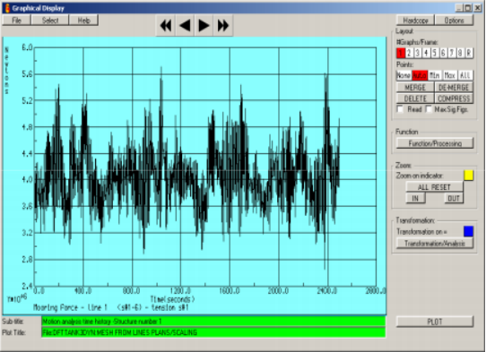
• AQWA Graphical
Supervisor (AGS) now able to present/animate cable dynamics results from intermediate positions along mooring lines
– Based on ana lysis results or separately defined boundary conditions
ASAS to Mechanical - Beams and Wave Theories
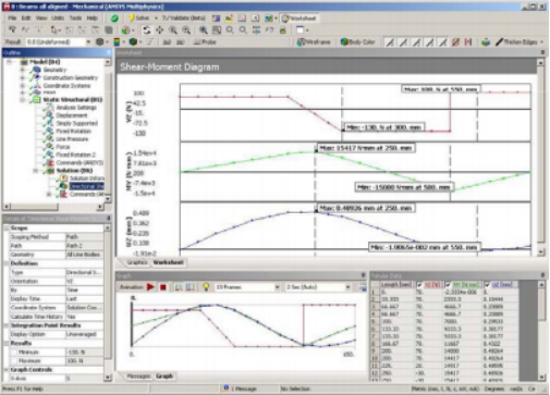
• Beam Post-Processing enhancements
– Shear Force and Bending
Moment diagrams
• Beam End-Releases
• Wave Theories
• Irregular waves
• Shell New Wave
• Constrained Wave
ASAS to Mechanical - Soil-Pile-Structure Interaction
• Soil/Pile Interaction Solver (SPLINTER) enhanced to work with Mechanical (via command snippets &
Matrix27 elements)
– PILEGEN and PILECALC macros included with the ASAS installation (capability only available via ASAS
Offshore license)
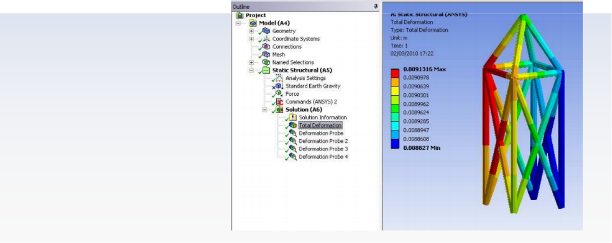
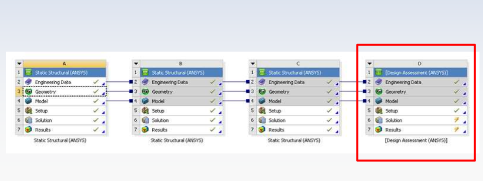
Design Assess ment - New System in Workbench
• Design Assess ment System
– Available with Professional NLS and above
– Post-an alysis assess ments of FEA results
– Load Case Combinations
• Static Structural
• Flexible Dynamics (at a specific time)
Design Assess ment - Customization
• Design Assess ment System
– Advanced post-processing of FEA results
• Targeted at user wanting to do design code
assess ment based on FEA models and results
– Predefined scripts supplied for ANSYS supplied code checking tools
– Enables the customer to define additional data that is associated with their model and then
perform custom post processing
• Custom definition of input data
• Custom result
• Custom Solve & Post scripts (Python based)
详细内容请见附件
免责声明:
本页面/内容部分素材来源于互联网公 开 信 息,旨在传递更多信息,不代表本平台立场。
版权归原作者或机构所有,如涉及侵权,请通过平台联系我们,我们将在核实后第一时间处理。
本平台对转载内容的真实性、准确性不作任何保证,用户需自行判断并承担使用风险。