中空型被动冲击隔离器Hollow Passive Shock Isolators设计

Abstract:
This study presents the design and performance evaluation of a hollow-type passive shock isolator for mitigating high-mass impact. The properties of the hyperelastic material were characterized through static tests and incorporated into a finite element model for design optimization. The isolator reduces shock trans mission in both vertical and horizontal directions, ensuring the structural safety of mounted equipment in modern weapon systems. Rubber, a typical hyperelastic material, exhibits strong elasticity but requires careful design to withstand repeated loads and high stresses without degradation.A prototype isolator was fabricated, and its shock absorption performance was validated by impact load testing. The results confirm that the proposed design effectively attenuates impact forces, demonstrating a strong potential for practical applications.
Keywords:
hyper-elastic material, large deformation, passive shock isolator, numerical study, material property, impact response
Introduction
In modern weapon systems, research on shock resistance performance continues to be conducted to ensure the structural integrity and operational reliability of onboard equipment. To secure omni-directional shock protection, not only vertical passive shock isolators mounted beneath the equipment but also horizontal shock isolators that can mitigate shocks trans mitted in the horizontal direction are employed together.Shock isolators effectively reduce external shock loads trans mitted to the equipment through supporting structures,and can be categorized by material type: hyperelastic materials such as rubber and polyurethane, metal-based coil springs, wire ropes, hybrid structures combining dissimilar materials, or compressible fluids such as air or oil.[1–6]They are further classified by operating mechanis m into passive,active, and semi-active types,[7–9] among which the passive type is most widely used due to its simple manufacturing process and relatively low technical complexity.
Rubber, as a representative hyperelastic material, exhibits strong nonlinear behavior in its stress–strain relationship up to the point of plastic deformation or permanent damage.This unique property is imparted through a thermal curing process, in which raw rubber is mixed with additives such as sulfur, organic peroxides, and metal oxides, and then heated to form cross-links between polymer chains. As a result, rubber becomes an elastic material with excellent resilience and recoverability. However, when exposed to repeated loading or high-temperature environments,[10] hyperelastic materials may experience changes in molecular structure, leading to a gradual reduction in stiffness. Under sustained high stress,permanent structural damage and accumulated deformation may occur. Therefore, designing hyperelastic-based isolators that can maintain stable shock isolation performance under high load conditions is considered a technically demanding challenge.
In this study, a hollow-type passive shock isolator was developed to mitigate high-mass impact loads. To achieve this, design and verification were carried out based on static load tests and finite element an alysis (FEM) of a hollowtype passive shock isolator employing hyperelastic material.Furthermore, the shock isolation performance of a fabricated
reference prototype was experimentally validated through shock load testing.
Experimental
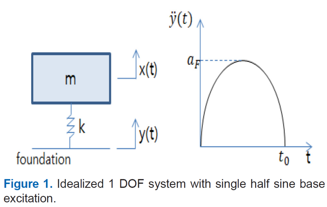
As shown in Figure 1, this study derived the appropriate stiffness that satisfies the target shock reduction ratio for a single-degree-of-freedom system subjected to a base shock with a half-sine time history. Given the system’s mass, the duration of the half-sine signal, and the desired shock reduction ratio, the corresponding stiffness can be determined using the
period of the half-sine signal. However, since actual shock signals often have irregular waveforms, obtaining an exact an alytical solution is challenging. Therefore, in this study, a numerical approach was employed to derive an approximate solution. Specifically, the fourth-order Runge-Kutta method was applied to determine the stiffness of the hollow-type passive shock isolator that meets the target shock reduction performance under the given design conditions.[11]
Results and Discussion
1. III-1 Material Property Test
In this study, to verify the target stiffness determined during the design specification stage, three different hardness levels of hyperelastic materials—designated as A, A+5,and A+15—were selected. Here, A represents the baseline hardness, while A+5 and A+15 correspond to hardness levels 5 and 15 points higher than A, respectively.
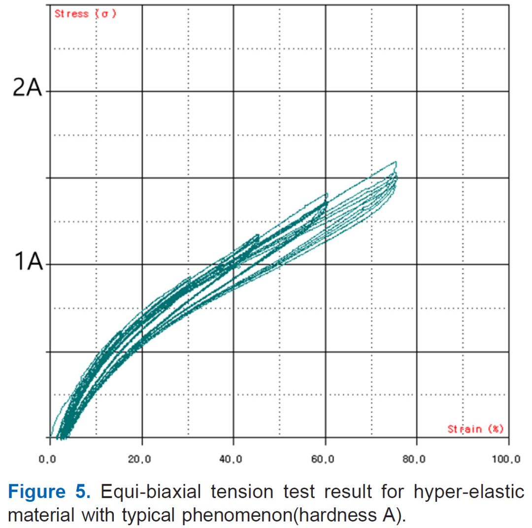
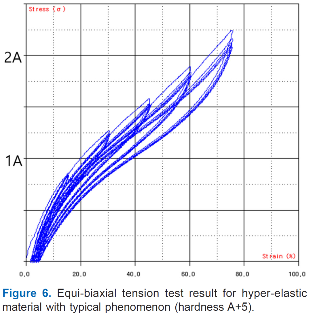
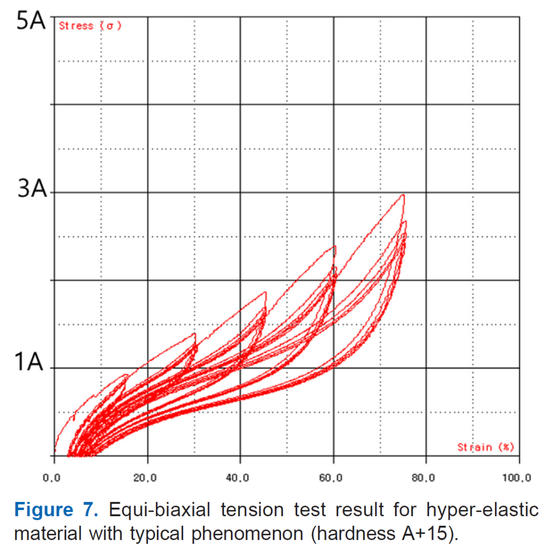
The stress–strain characteristics were evaluated to fabricate a hollow-type passive shock isolator with the desired shock reduction performance. To obtain the stress–strain behavior,uniaxial (Figures 2-4) and biaxial (Figures 5-7) tensile tests were conducted. In the biaxial tensile test, the specimen was subjected to maximum strain levels of 15%, 30%, 45%, 60%,and 70%, with five loading cycles performed for each strain level.
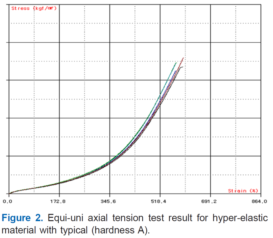
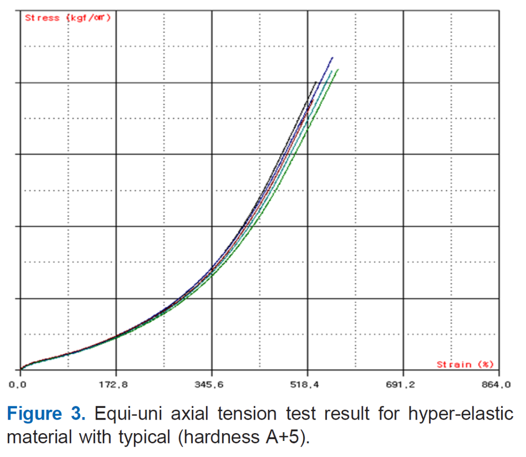
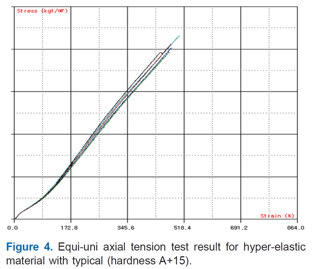
The test results confirmed the occurrence of the Mullins effect,[12] a phenomenon where the material undergoes irreversible softening and a change in its properties under repeated displacement or loading. To ensure stable material property data, it is common practice to apply approximately five repeated displacement or loading cycles until the peak stress values or stiffness reduction rates stabilize within an acceptable range, after which the results are used. Additionally,as shown in Figures 5-7, permanent deformation of the rubber was observed during repeated tensile loading.
Therefore, in this study, the final cycle results from the repeated loading tests at each strain interval were used, with permanent deformation off set, to evaluate the stress–strain characteristic curve. Based on this, the hardness level B+25 was selected to meet the target design requirements.
Meanwhile, in the case of hyperelastic materials, as shown in Figures 5-7 the stress–strain or load–displacement behavior varies depending on the loading and unloading conditions,forming a hysteresis loop. Therefore, different stress–strain characteristics can be evaluated for each loading condition.In this study, the stress–strain curve under the static loading conditions relevant to the applied loads was determined and used as input data for the compression an alysis of the reference prototype.
2. III-2 Static Compression Test and A nalysis of the Reference Prototype
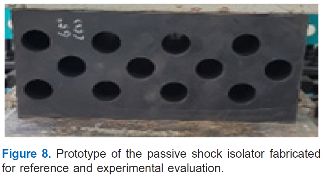
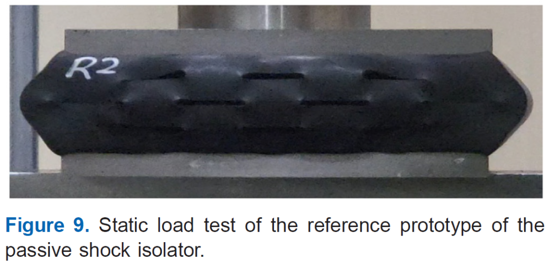
In this study, the reference prototype shown in Figure 8 was first fabricated, and a compression test was conducted as illustrated in Figure 9. The static tensile and compression tests for the reference prototype were performed under displacement-controlled conditions with a maximum displacement of up to -50 mm.
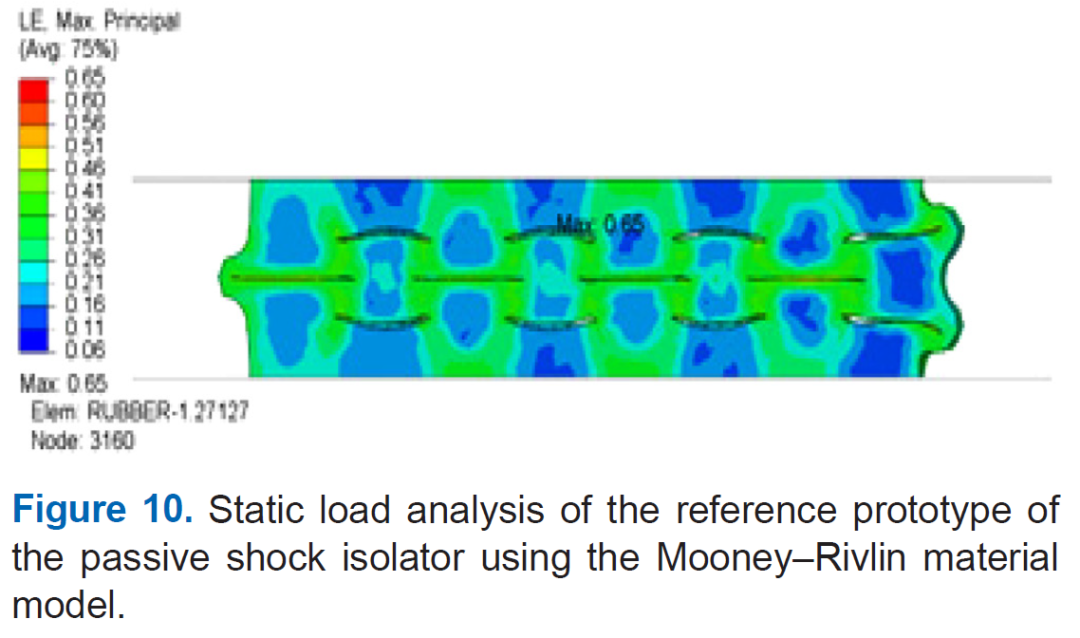
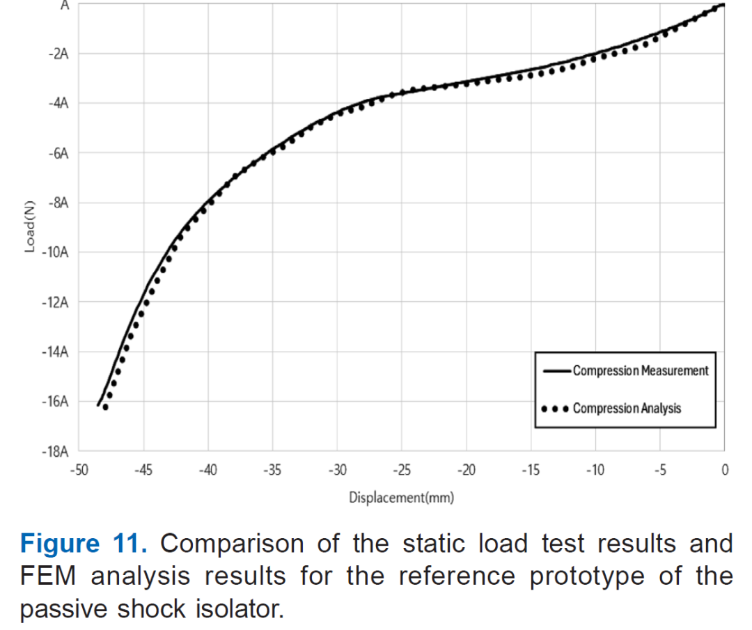
Additionally, under the same conditions, a numerical an alysis model based on the reference prototype was developed, and a static compression an alysis was carried out as shown in Figure10. For materials with nonlinear stress–strain relationships,such as hyperelastic materials, it is crucial to select a reliable material model that can accurately replicate the behavior of the target material in numerical an alyses. Accordingly, in this study, the general-purpose finite element a nalysis software midas NFX was used, employing the Mooney–Rivlin model as the hyperelastic material model. The material properties obtained from experimental tests at different strain levels were applied to the an alysis. The similarity between the a nalysis results and the experimental results for the reference prototype was confirmed, as shown in Figure 11. The reference prototype employed in this test was designed to be attached to the wall in the actual installation, such that it is subjected only to compressive loads. Accordingly, both the experimental evaluation and numerical an alysis were conducted under compressive loading conditions.
3. III-3 Impact Load Test of the Reference Prototype
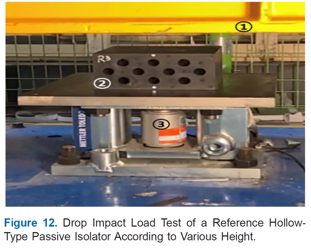
The fabricated reference prototype (②) was tested as shown in Figure 12 by dropping a weight of 664 kg (①)from heights of 100 mm, 200 mm, and 300 mm. The impact load after absorption was measured using a load cell (③).The shock absorption rate, calculated as the reduction in impact load compared to the potential energy at each drop height, is summarized in Table 1. The tests at 100 mm and 200 mm showed an absorption rate of approximately 40%, while the 300 mm test showed a lower rate of about 20%. This is because, in the 100 mm and 200 mm tests, the hollow structure closed under the impact, resulting in higher absorption. However, in the 300 mm test, after the hollow closed, additional impact load was still trans mitted, leading to a lower overall absorption rate.

Conclusions
In this study, a hollow-type passive shock isolator based on a hyperelastic material was designed to reduce high-mass impact loads, and its performance was verified through static and impact tests. A material satisfying the target stiffness derived from numerical a nalysis was selected, and the validity of the design was confirmed through static compression tests and finite element an alysis. Drop impact test results quantitatively confirmed the shock absorption effect of the hollow structure depending on the drop height, showing an absorption rate of approximately 40% at 100 mm and 200 mm, and about 20% at 300 mm. These findings demonstrate the effectiveness of the proposed design procedure for the hollow-type passive shock isolator. Future research will focus on performance improvement through optimization of the hollow structure shape.
References
1.T. K. Ahn and K. W. Kim, “Identification Method of the Dynamic Characteristics of Pre-deformed Elastomers”, Transactions of the Korean Society for Noise and Vibration Engineering, 13, 918 (2003).
2.H. H. Kwon and J. J. Choi, “Design Automation of the Compressive Coil Spring”, Journal of the Korea Society of Machine Tool Engineers, 9, 140 (2000).
3.J. B. Park, G. G. Yoon, B. H. Bae, S. G. Lee, and S. H. Lee, “Design of Wire Rope snubbers”, Proceedings of the KSNVE Annual Spring Conference, 1192 (2000).
4.Y. H. Shin, J. H. Lee, B. C. Jung, and S. J. Moon, “Design of Passive Vibration Isolation Element by Wire Mesh Material for Developing a Hybrid Mount”, Transactions of the Korean Society for Noise and Vibration Engineering, 30, 75 (2020).
5.Y. K. Ahn and D. W. Kim, “Hybrid Rubber Mount by Using Magnetic Force”, Transactions of the Korean Society for Noise and Vibration Engineering, 24, 236 (2014).
6.J. H. Kim, D. W. Lee, and J. S. Kim, “Development of Air-Damping Mount”, Proceedings of the KSNVE Annual Autumn Conference, 328 (2009).
7.D. O. Lee and J. H. Han, “A Comparison of Vibration Isolation Characteristics of Various Forms of Passive Vibration Isolator”, Proceedings of the KSNVE Annual Autumn Conference, 232 (2012).
8.S. M. Choi, S. J. Moon, W. J. Jung, and J. Y. Koo, “Development of 500 kg Class Active Hybrid Mount for Naval Ships”, Proceedings of the KSNVE Annual Spring Conference, 152 (2010).
9.S. Y. Yang, I. D. Kim, S. J. Kim, J. Y. Jung, and S. B. Choi, “Design of Semi-active Magneto-rheological Mount for a Cabin of Wheel Loader for Vibration Control”, Proceedings of the KSNVE Annual Spring Conference, 624 (2016).
10.I. S. Hwang, T. S. Ahn, and D. H. Lee, “Variability A nalysi of Dynamic Characteristics in Rubber Engine Mounts Considering Temperature Variation”, Transactions of the Korean Society for Noise and Vibration Engineering, 23,
553 (2013).
11. T. M. Choi and J. T. Kim, “Design of a Payload Passive Shock Isolation Using a Material Properties Test and Numerical Study on Hyper-elastic Materials”, Transactions of the Korean Society for Noise and Vibration Engineering,
35, 1 (2025).
12. S. H. Oh, S. Y. Lee, J. H. You, H. S. Kim, S. K. Cheong,and K. H. Shinm, “Temperature-dependent Mullins Effect in Anti-vibration Rubber For Railway Vehicles”, Journal of the Korea Society of Manufacturing Technology Engineers,
26, 193 (2017).
AUTHOR:

DOI: https://doi.org/10.7473/EC.2025.60.3.110