Deform Heat Treatment Wizard Lab(热处理模块向导)

摘要:
本文介绍 DEFORM 热处理向导(Heat Treatment Wizard)的完整操作流程,以齿轮渗碳–淬火–回火为例,演示多工序热处理仿真。流程包括新建问题、初始化、几何导入、网格划分、材料定义、工件初始条件、热处理介质设置、工艺曲线定义、仿真控制、提交计算及后处理。向导支持变形、扩散、相变耦合计算,可设置加热、渗碳、油淬、回火、空冷五阶段工艺,自定义换热系数与表面反应速率。后处理可查看温度、碳浓度、各相体积分数与残余应力,适合钢件热处理相变与应力场快速建模,操作简便、工程实用性强。
HEAT TREATMENT WIZARD LAB
1.Starting a new problem 1
2.Initialization 1
3.Import geometry 2
4.Generate mesh 2
5.Material definition 3
6.Workpiece initialization 5
7.Medium definition 5
8.Schedule definition 7
9.Simulation control 7
10. Submit simulation 9
11. Post processing 10
Problem Summary:
The Heat Treatment Wizard is a convenient tool to set up complex multiple-operation heat treatment problem. This lab will demonstrate how to use this wizard to prepare a carburization- quench-tempering simulation of a steel part. This lab can also help users understand the capabilities of DEFORM-HT's phase transformation calculation scheme.
1.Starting a new problem
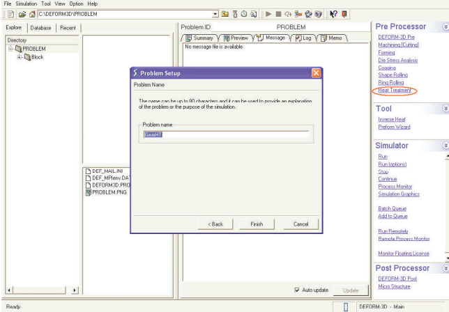
Start a new Heat Treatment Wizard problem with problem ID "GearHT". You can do so by clicking the “New problem” button and choose “Heat treatment”. Alternatively, you can right click on the directory tree to create an empty directory and click “Heat treatment” on the right side of the main window.
2. Initialization
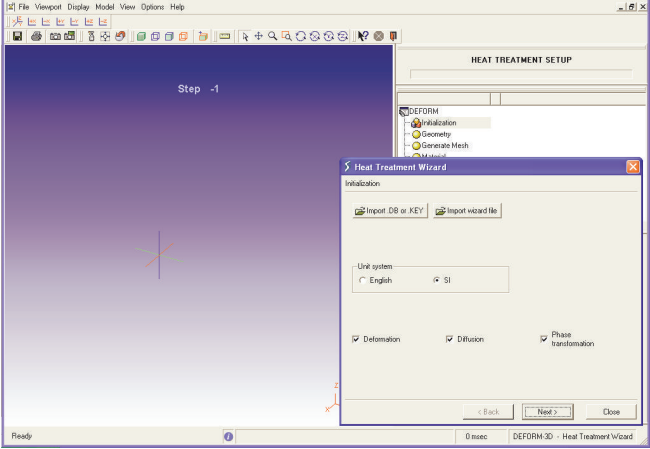
In the "Initialization" dialog, set the "Unit System" to SI. Turn on "Deformation", "Diffusion", and "Phase Transformation". Click "Next".
DEFORM™-Heat Treatment Wizard Lab
3.Import geometry
In page “Geometry”, choose “import from a geometry, KEY, or DB file” and click “Next”. Go to directory Labs/, and load geometry file “GearTooth.STL”.
4.Generate mesh
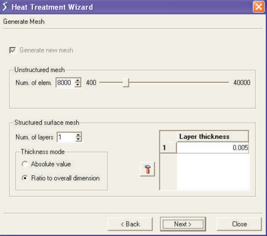
In page “Mesh Generation”, use 8000 for unstructured mesh. Use 1 layer of structured surface layer, set "Thickness mode" to be "ratio to object overall dimension", and 0.005 for the layer thickness. (The structured surface mesh helps provide better thermal and diffusion solution accuracy with less computing time.) Click “Next”.
DEFORM™-Heat Treatment Wizard Labs
5.Material definition
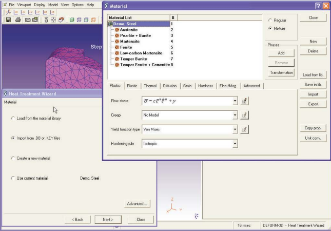
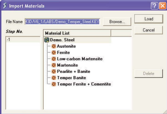
In page “Material”, choose “Import from .DB and .KEY” and click “Next”. Import material "Demo Temper Steel.KEY" from directory labs/.
You can click button "Advance" to view and edit the material and transformation data.
Note that this is a complex mixture material with eight constituents (phases), including Austenite (A), Pearlit+Banite (PB), Martensite (B), Ferrite (F), Low-carbon Martensite (LM), Temper Banite (TB), Temper Ferrite+Cementite (TFC). The transformation kinetics between the phases include A->F, A->PB, A->TB, A->M, PB->A, M->LM, M-
>A, LM->TFC, TB->A, and TFC->A. Among these kinetics, A->F, A->PB, A->TB, M-
>LM, and LM->TFC are diffusion-controlled defined by TTT curves. A->M uses Martensitic transformation model, and PB->A, M->A, TB->A, and TFC->A use simplified diffusion model. In addition, A->F has an equilibrium volume fraction that depends on carbon contents.
DEFORM™-Heat Treatment Wizard Lab
DEFORM™-Heat Treatment Wizard Labs
6.Workpiece initialization
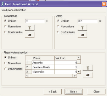
In page "Workpiece initialization", for "Temperature", choose "Uniform" and set 20 C. For "Atom", choose "Uniform" and input 0.2. For "Phase volume fraction", choose "Uniform" and set 1.0 for "Pearlite + Banite", and zero for the rest.
7.Medium definition
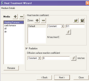
In page “Medium details”, you will define various media and heat transfer zones associated with them.
1)Rename the first medium to “Heating Furnace” and set the “default” heat transfer coefficient (HTC) to constant 0.1.
DEFORM™-Heat Treatment Wizard Lab
2) Add medium “Carb. Furnace” (Carb. for Carburization). Set the “default” heat transfer coefficient (HTC) to constant 0.05.
For “Carb. Furnace”, input 0.0001 for the "Diffusion Surface Reaction Rate".
3) Add a media “Oil”. Deactivate the "Radiation".
Input 5.5 for the "default" HTC.
Add a heat transfer zone (Zone #1) to the media “Oil”. Click on the workpiece boundary to specify this zone to the bottom of the workpiece as shown in the graph below. Note that you may need to change the picking modes in the low-left window in order to specify the zone properly.
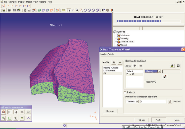
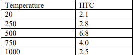
For Zone #1, define the HTC as a function of temperature as follows:
4)Add one more media “Air”. Input 0.02 for the default HTC.
8.Schedule definition
In “Schedule” page, input a five-stage schedule as explained below.
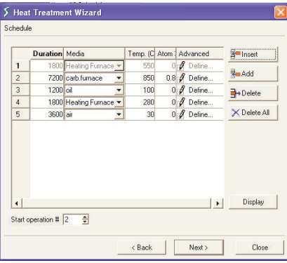
1)Half an hour (1800 s) of pre-heating at 550C.
2)Two hours (7200 s) of carburization at 850C. Specify the "Atom" content to be 0.8.
3)20 minutes (1200 s) of oil quench with oil temperature 100C.
4)30 minutes (1800 s) of tempering at 280C.
5)One hour (3600 s) cooling in the air.
9.Simulation control
In "Step Definition", change "Temp. change per step" to 2. Accept other default settings.
Next, two symmetric planes need to be specified as in the following graph. (Note that this geometry represents half a tooth of the gear.) The user should add the "symmetric planes" before picking corresponding surface on the object.
DEFORM™-Heat Treatment Wizard Lab
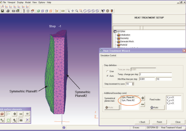
In addition, as elasto-plastic deformation will be modeled, some fixed-node boundary conditions need to be specified here. To do so, select a boundary condition item and then assign it to appropriate boundary nodes. For this model, as the symmetric planes provide X, Y direction and rotational constraints, we only need constraints in the Z direction. Here, we fix a node on the bottom as shown in the following graph.
DEFORM™-Heat Treatment Wizard Labs
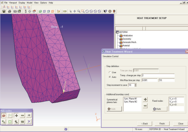
Next, click "Finish" button to generate the Keyword file (.KEY), Database file (.DB) and multiple operation control file (.MST).
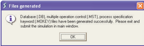
10.Submit simulation
Exit Heat Treatment Wizard and click "Run" in the Main window, just like submitting a regular simulation. DEFORM simulation engine will detect the multiple operation control file and execute accordingly.
DEFORM™-Heat Treatment Wizard Lab
11.Post processing
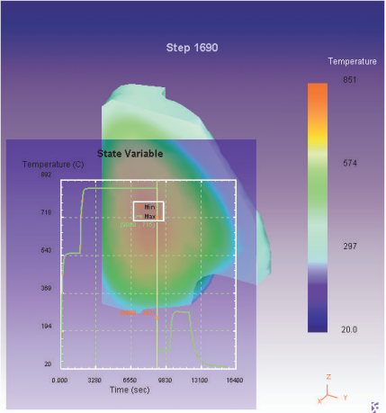
After the simulation is completed, use Post Processor to view the simulation results. The temperature min-max history should be like the graph blow:
In post-processing, we recommend following tasks to be performed:
1.Examine the state of the work-piece after oil quenching. The state variables of interest may include carbon content, volume fractions of Martensite (M), Ferrite (F), and Perlite + Banite (PB), and the residual stress. Note that at this point, M is as high as 0.77 near tooth surface, and the maximum effective stress is ~470 KSI. (Such high stress may not exist in real life as the work-piece cracks.)
2.Check the same state variables after tempering. Note that M is reduce to ~0.2 near tooth surface, most of which is transformed into Tempered Ferrite + Cementite (TFC). The maximum effective stress is reduced to ~180 KSI
3.In addition, point tracking phase volume fractions at different locations of the work- piece can be helpful for understanding the complex phenomena occurred during the carburization and heat treatment.
更多内容见附件
免责声明:
本页面/内容部分素材来源于互联网公 开 信 息,旨在传递更多信息,不代表本平台立场。
版权归原作者或机构所有,如涉及侵权,请通过平台联系我们,我们将在核实后第一时间处理。
本平台对转载内容的真实性、准确性不作任何保证,用户需自行判断并承担使用风险。