摘要:本文为 ANSYS Workbench 15.0 官方用户指南,全面讲解仿真平台操作与工程应用流程。指南覆盖界面布局、项目原理图、系统搭建、数据链接与参数化设计,详述几何建模、网格划分、材料设置、载荷约束、求解与后处理全步骤。支持结构、流体、热、电磁、多物理场耦合及水动力等多类型分析系统,包含 Design Exploration 参数优化与设计点管理。同时介绍远程求解管理器 RS M、日志脚本、文件归档、EKM 数据管理及常见故障排查,提供标准化建模、求解与协同仿真规范,为多物理场仿真全流程提供权威操作指导。Workbench User's GuideCopyright and Trademark Information© 2013 SAS IP, Inc. All rights reserved. Unauthorized use, distribution or duplication is prohibited.ANSYS, ANSYS Workbench, Ansoft, AUTODYN, EKM, Engineering Knowledge Manager, CFX, FLUENT, HFSS and any and all ANSYS, Inc. brand, product, service and feature names, logos and slogans are registered trademarks or trademarks of ANSYS, Inc. or its subsidiaries in the United States or other countries. ICEM CFD is a trademark used by ANSYS, Inc. under license. CFX is a trademark of Sony Corporation in Japan. All other brand, product, service and feature names or trademarks are the property of their respective owners.Disclaimer NoticeTHIS ANSYS SOFTWARE PRODUCT AND PROGRAM DOCUMENTATION INCLUDE TRADE SECRETS AND ARE CONFID-ENTIAL AND PROPRIETARY PRODUCTS OF ANSYS, INC., ITS SUBSIDIARIES, OR LICENSORS. The software products and documentation are furnished by ANSYS, Inc., its subsidiaries, or affiliates under a software license agreement that contains provisions concerning non-disclosure, copying, length and nature of use, compliance with exporting laws, warranties, disclaimers, limitations of liability, and remedies, and other provisions. The software products and documentation may be used, disclosed, transferred, or copied only in accordance with the terms and conditions of that software license agreement.ANSYS, Inc. is certified to ISO 9001:2008.U.S. Government RightsFor U.S. Government users, except as specifically granted by the ANSYS, Inc. software license agreement, the use, duplication, or disclosure by the United States Government is subject to restrictions stated in the ANSYS, Inc. software license agreement and FAR 12.212 (for non-DOD licenses).Third-Party SoftwareSee the legal information in the product help files for the complete Legal Notice for ANSYS proprietary software and third-party software. If you are unable to access the Legal Notice, please contact ANSYS, Inc.Published in the U.S.A.OverviewANSYS Workbench combines the strength of our core simulation tools with the tools necessary tomanage your projects. You will work with your ANSYS Workbench project on the main project workspace, called the Project tab. The project is driven by a schematic workflow, represented visually on a flowchart- like diagram called the Project Schematic. To build an a nalysis, you add building blocks called systemsto the Project Schematic; each system is a block of one or more components called cells, which rep-resent the sequential steps necessary for the specific type of an alysis. Once you have added your systems, you can link them together to share and/or transfer data between systems.From the cells in the Project Schematic, you can work with various ANSYS applications and ana lysistasks. Some of these open in tabs within the Workbench environment, while others open independently in their own windows.ANSYS applications allow you to specify parameters such as geometry parameters, material propertiesand boundary conditions. Parameters can be defined within the application and managed at the project- level in the Workbench environment.To perform your a nalysis, you will work through the cells of each system in order—typically from top to bottom—defining inputs, specifying project parameters, running your simulation, and investigating the results.Workbench enables you to easily investigate design alternatives. You can modify any part of an an alysis or vary one or more parameters, and then automatically update the project to see the effect of thechange on the simulation result.Related Topics:Interacting with Project ObjectsWorkbench Tabs and Views The Project TabInteracting with Project ObjectsIn ANSYS Workbench, a Toolbox on the left side of the Project tab contains an alysis systems, component systems, and other types of project objects. The Project Schematic view will contain the system(s) thatyou have added, with each system made up of one or more cells. You can interact with these project objects in a number of different ways:• Single-click: Single-click an object to select it. This does not modify data or initiate any action.• Double-click: Double-click an object to initiate the default action. This allows users who are familiar with ANSYS Workbench to quickly move through basic or common operations.• Right- click: Right-click to display a context menu applicable to the current state of the selected object. From the context menu, you can select from multiple actions. The default action is shown in bold and is the action that will occur if you double-click the object.• Drag-and-drop: Drag-and-drop an object to preview possible locations for it on the Project Schematic. A drag-and-drop operation can have multiple alternative targets, depending on context and schematiccomplexity. Holding down the mouse button, hover over any target to see details of how the target location would be implemented (for example, what components would be connected after the operation is com-pleted).To cancel a drag-and-drop operation, press the Esc key while holding down the mouse button.Workbench Tabsand ViewsWhen working in the Workbench environment, you will be dealing primarily with interface elements called tabs and views.Workbench TabsIn Workbench, tabs serve as workspaces that allow you to interact with different parts of your project. In addition to the Project tab, other tabs can be opened for other workspaces; for example, you canopen the Parameter Set tab by double-clicking on the Parameter Set bar on the Project Schematic. Workspace tabs can be accessed either by double-clicking the associated cell, or by right-clicking it and selecting Edit.Each cell that does not launch an external application has a single workspace that can be opened inside Workbench. In some cases, it may be possible to open multiple tabs of the same type; for instance, ifyou have three Engineering Data cells in three separate systems, you could have three Engineering Data tabs open at the same time.Tabs in Workbench are made up of multiple views containing information relevant to portion of thea nalysis shown in the tab. Each tab also has a context-specific toolbar containing buttons for the oper- ations that are available, given the current state of the project.You can click on tabs to move between them or right-click them to view available context menu options such as Close Tab, Close Other Tabs, and Close All. You can also close individual tabs by clicking the“x” icon. Only the Project tab cannot be closed.For more information, see Tabs within Workbench (p. 245).Workbench ViewsTabs in Workbench are made up of multiple views that can be reconfigured according what information you want to be shown in the tab.Some views are common to multiple tabs, while others are tab-specific. Some views are only shown in the tab for which they’ve been enabled, while others, once enabled, are shown across all the tabs either until you either disable them or reset the tab layout.The configuration and persistence of the views across tabs varies to give you the maximum flexibility in customizing the information you see on each tab. The header bar of each view contains icons and context menus that allow you to control view attributes such as visibility, size, and floating/docked state. You can access the context menu either by clicking the down-arrow or by right-clicking in the header.• To open a view, select it from the View menu. For example, if you’re in the Project tab and select View > Outline, the Outline view will be shown in the Project tab. Once the view is open, it will update its content according to the what you’ve selected; by selecting different objects, you can view or edit the associated properties of those objects.• To close a view, deselect it from the View menu, select Close from the header bar context menu, or click the “x” icon in its header bar.• To change how the view displays, use the Minimize, Maximize, and Restore context options. – When you minimize a view, it appears as a tab in the bottom left corner of the ANSYS Workbench window. You can only maximize a floating view; you cannot maximize a docked view. – After you have maximized a view, use the Restore option on the Windowing drop-down menu to return the view to its pre-maximized size and location.• To resize a view, you can use your mouse to drag its edges to the desired size.• You can also “float” and “redock” views. By default, most views are “docked,” or embedded in their tab. By default, most views are embedded in their tab. You can choose to separate a view from its tab, so it can be moved outside of the Workbench window. When you redock a view, it returns to its place on its usual tab.When you float a view, you separate it from its tab, so it is still available when you switch tabs. This is especially useful when you want to see a view that is not available as part of a tab. For example, the Files view is not visible in the Parameter Set tab, but you can float the Files view so you can see it while working with project parameters. – To float a view, select the Float context option or the thumbtack icon in the view header. You can also “tear” the view from its dock by dragging the header with your mouse. – To redock a view, select the Redock context option or the thumbtack icon in the view header. When you redock a view, it will return to its normal tab and may not be visible in the current tab. You can also select the View > Reset Workspace menu option, which resets the views in the current tab to their default positions. – You can reset the views for one tab or for all the tabs. → To reset all the views in the current tab to their default position, select View > Reset Workspace. → To reset all the views in the project,, select View > Reset Window Layout. This resets the views in all tabs to their default positions and opens the Project tab.Some views—for example, the Table, Chart, Outline, and Properties views—are defined per tab, sothat changes to a view are specific to that tab. For example, if you resize and float the Chart view inthe Parameter Set tab and then switch to the Response Surface tab in a DesignXplorer system, you’ll find that the Chart view in the new tab will note be resized and floated. (The DX Chart view containsdifferent data, and so does not reflect the changes made to the Chart view elsewhere.) When you return to the Parameter Set tab, you’ll see that the Chart view there is resized and floated, as before.For more information on specific views, see Views within Tabs (p. 245).The Project TabWhen you open a project in ANSYS Workbench, it opens to the Project tab. The Project tab is just one of many tabs that can be opened in Workbench, but it is the main workspace in which you will build your an alysis.Like all tabs, the Project tab is made up of different views that can be reconfigured according the in-formation you want to see. By default, the Project tab is comprised of the Toolbox view and the Project Schematic view. Related Topics: The Toolbox in the Project Tab The Project SchematicThe Toolbox in the Project TabThe Workbench Toolbox view contains the types of data you can add to your project.In the Project tab, the Toolbox contains the different types of systems you can add to the ProjectSchematic. Systems are divided into categories which can be expanded or collapsed to show or hide the systems in that category. You can select systems from the following categories: An alysis Systems (p. 135) Component Systems (p. 149) Custom Systems (p. 240) Design Exploration (p. 242) External Connection Systems (p. 243) The contents of each category are determined by which products you have installed and what licenses are available. If you do not have a particular product installed or do not have an available license, the individual systems corresponding to that product will not be shown in the Toolbox. Additionally, you can customize the Toolbox further, specifying that only some of the available systems are visible.The Toolbox view persists across tabs. It contains systems on the Project tab, but on other tabs it will contain other sorts of information, such as charts, engineering materials, etc.For information on customizing the Toolbox on the Project tab, see Customizing the Toolbox on the Project Tab (p. 9).For detailed information on system categories and individual systems, see ANSYS Workbench Sys- tems (p. 135).The Project SchematicWhen you interact with a simulation project, you will work primarily in the Project Schematic view of the Project tab, adding systems from the Toolbox to the project and then working with those systems.Projects can vary in complexity, from a single system representing all the necessary steps for a desired a nalysis, to a complex set of connected (linked) systems representing coupled an alyses or variations in modeling approaches.NoteIt is recommended that a given project contains only systems that are relevant to a specificana lysis or coupled an alysis with a well-defined focus. Adding systems for multiple unrelated ana lyses to the same project can have an adverse effect on performance and cause corruption with portions of the project.Related Topics: Systems and Cells in the Project Schematic Project Schematic Links Project Schematic WorkflowSystems and Cells in the Project SchematicEach system placed on the Project Schematic is made up on one or more ana lysis components called cells. Once all of your systems are in place, you’re ready to start defining the details of your an alysis.To do so, you generally interact with systems at the cell level. Right-click the system header or cell to see a menu of available options; double-click to perform the default action (bolded in the contextmenu).You can interact with a cell to perform any of the following actions: • launch an application that opens independently of Workbench • open a tab inside Workbench • add connecting systems, either upstream or downstream • assign input or reference files • assign properties to components of your ana lysisEach cell has either an application or a tab associated with it. Some cells are associated with an applic- ation that launches in a separate window, such as Fluent or Mechanical; in some cases, multiple cellsin a system can be associated with the same application. Other cells, such as the Parameters cell or a cell in a System Coupling system, are associated with tabs that open inside Workbench.NoteThe Project Schematic may reflect actions you take in applications that open independently of Workbench.To add a system to your project, you can drag a system from the Toolbox and drop it on the Project Schematic; alternatively, you can double-click the desired system in the Toolbox. Once you’ve added systems to the Project Schematic, you can create links between cells to transfer and/or share data. For information on building and linking systems, see Working in the ANSYS Workbench Project Tab (p. 33).Icons for each cell indicate the state of that particular cell—for example, whether the cell needs attention, is up-to-date, and so on. For more information, see Understanding Cell States (p. 255).To display a quick help panel for the cell, click the blue triangle in the lower right corner of the cell (where available). The quick help message that displays will explain any immediate action that needs to be taken and may include links to more detailed help.Project Schematic LinksLinks connecting systems represent data sharing or data transfer between the systems. The primary kinds of links that may be shown in the Project Schematic include: • Links indicating that data is shared between systems. These links are shown with square terminators; see the figure below. • Links indicating data is transferred from an upstream system to a downstream system. These links are shown with round terminators; see the figure below. • Links indicating a system is consuming input parameters. These links connect systems to the Parameter Set bar and are drawn with arrows going into the system, as shown in the figure below. • Links indicating a system is providing output parameters. These links connect systems to the Parameter Set bar and are drawn with arrows coming out of the system, as shown in the figure below. • Links that indicate a Design Exploration system is connected to project parameters. These links connect Design Exploration systems to the Parameter Set bar, as shown with the Design Exploration systems in the figure below. • Links indicating that data is transferred from a Design Exploration Response Surface to a Parameters Correlation, as shown with systems E and F in the figure below. • Links indicating that design point data is transferred from a Design Exploration component to a Design Exploration Direct Optimization system. For more information, see Transferring Design Point Data for Direct Optimization in the Design Exploration User's Guide.Additional information on working with links can be found in Creating and Linking a Second Sys- tem (p. 43) and Moving, Deleting,and Replacing Systems (p. 48).Working with Shared Data LinksLinks that are drawn with a square terminator indicate that data is shared between the two systems.Only one instance of the data exists and it is shared between the connected systems. In order to editthe details of that data, you must edit the cell on the upstream system connected via these links. Inthe example shown in the figure above, the Geometry cell from system A is shared with the Geometrycell in system B, which is in turn shared with the Geometry cell of system C. In order to edit the geometry for ANY of these systems, you must initiate the edit operation from the Geometry cell in system A (bydouble-clicking on the cell or right-clicking on the cell and selecting Edit from the context menu).In many cases, it is possible to delete shared data links by right-clicking on the link and selecting Delete from the context menu. The data associated with the cell in the upstream system will be copied to the downstream system so the cells can be edited independently.In some cases, you will not be able to delete links. In these cases, the linked cells in the downstream system will be shown with a gray background (as shown in systems C and E, above).Project Schematic WorkflowTo complete your a nalysis, you will work downward through each cell in order. In general, data flowsdownstream (from top-to-bottom within systems and from left-to-right across systems). Output data from upstream component cells is provided as the input data for downstream cells. Output data from certain types of cells in one system can also be transferred and/or shared with cells in another system.The following example shows two systems in the Project Schematic, a Fluid Flow (Fluent) system (system A) and a Static Structural system (system B). In this example:• The geometry from the Geometry cell in system A becomes the input for the Mesh cell that is downstream in that system. The mesh generated in the Mesh cell of the system, in turn, becomes input to the down-stream Setup cell, and so on.• There is also data-flow between ystem A and system B, as follows: – They share the same geometry, as indicated by the connector with the square terminator between the Geometry cell in system A and the Geometry in system B. – Solution data from System A is provided to the Setup cell of system B, as indicated by the connector with the round terminator.At a glance, you can see the data relationship between the two types of an alysis systems.Configuring ANSYS WorkbenchInformation about configuring ANSYS Workbench can be found in the following sections: Customizing the Toolbox on the Project Tab Configuring Units in Workbench Setting ANSYS Workbench Options Using Software Licensing in ANSYS WorkbenchCustomizing the Toolbox on the Project TabWhen you open ANSYS Workbench, the Toolbox view on the Project tab contains different systems you can add to your project, divided into five categories: An alysis Systems (p. 135) Component Systems (p. 149) Custom Systems (p. 240) Design Exploration (p. 242) External Connection Systems (p. 243)For descriptions of system categories and individual systems, see ANSYS Workbench Systems (p. 135).In the Toolbox view, the specific systems included in each category depend on what products youhave installed and the availability of licenses. If you do not have a product installed or do not have an available license, the systems corresponding to that product cannot be displayed in the Toolbox. Toget more information on a product that is discussed in the documentation but you do not see in your Toolbox, go to the Support page of the ANSYS Customer Portal and submit an online support request. For further information about tutorials and documentation on the ANSYS Customer Portal, go to ht-tp://support.ansys.com/docinfo.The Toolbox Customization view, accessed via the View All / Customize button at the bottom of the Toolbox, shows a list of all the systems available in your installation of ANSYS Workbench. You canspecify whether available systems will be visible in the Toolbox, customizing the display to show only the systems you use frequently. Select systems to show them in the Toolbox, or deselect systems to hide them. When you’re finished, click << Back to close the Toolbox Customization view.Configuring Units in WorkbenchANSYS Workbench provides the following functionality for unit systems:• a set of predefined unit systems that define most commonly used quantity units• the ability to define custom unit systems based on the predefined unit systems• the ability to display the following project data in project unit system: – engineering data – parameters – charts• the ability to share the unit system between different users via Import and Export optionsNoteUnit settings in ANSYS Workbench are not passed to Fluid Flow an alysis systems; to CFX, Fluent, Results, or TurboGrid systems; or to FSI: Fluid Flow custom systems.To access the Unit Systems dialog box, choose Units>Unit Systems from the menu bar. You will see the following:The following options are available from the Unit Systems dialog box:UnitsA unit system is a collection of the preferred unit for the base, common, and other quantity types.• Base Units: All other units are derived from these units. – Angle – Chemical Amount – Current – Length – Luminance – Mass – Solid Angle – Time – Temperature• Common Units: These are units which are derived from the base units and are typically used as base units for other units. – Electric Charge – Energy – Force – Power – Pressure – Voltage• Other Units: Several other units are derived from base and common units.For detail description on how units are used in expressions, see Expressions, Quantities, and Units (p. 98).Predefined Unit SystemsANSYS Workbench offers the following predefined unit systems: • Metric (kg, m, s, °C, A, N, V) (default unit system) • Metric (tonne, mm, s, °C, mA, N, mV) • U.S. Customary (lbm, in, s, °F, A, lbf, V) • SI (kg, m, s, K, A, N, V) • U.S. Engineering (lbm, in, s, R, A, lbf, V)You cannot edit or delete predefined unit systems.ANSYS Workbench also provides the following additional unit systems. These are suppressed by default. • Metric (g, cm, s, °C, A, dyne, V) • Metric (kg, mm, s, °C, mA, N, mV) • Metric (kg, µm, s, °C, mA, µN,V) • Metric (decatonne, mm, s, °C, mA, N, mV) • U.S. Customary (lbm, ft, s, F, A, lbf, V) • Consistent CGS • Consistent NMM • Consistent µMKS • Consistent BIN • Consistent BFTFor a detailed description of unit systems for the Mechanical application, see Solving Units.You can also display values as defined and display values in project units. See Units Menu (p. 264) for more information on using these options.Custom Unit SystemsUse the Duplicate option to create a custom unit system based on a predefined unit system.• The default name for the new Unit system is Custom Unit System. You can change the name.• You can change the units for any quantity type from the available list.• The list of units that are available are either consistent with SI or US Customary, depending on the original unit system. This to assure that a consistent unit system can be constructed for solution purposes.• Changing base units can automatically change Common and Other derived units if appropriate. For ex- ample, if the mass unit is kg, the length unit is m, and the force unit is N, then changing mass to g and length to cm will automatically change force to dyne.Setting ANSYS Workbench OptionsSelect Tools > Options to set your preferences for ANSYS Workbench. The preferences you set hereare local settings, affecting only you. Some changes made via the Options dialog will take place imme- diately, while others won’t take place until you start a new session.Use the Restore Defaults button to reset the settings visible on the current page to their default values; settings on other pages will remain unchanged.You can set user preferences in the following categories: Project Management Appearance Regional and Language Options Graphics Interaction Journals and Logs Project Reporting Solution Process Repository Extensions Mechanical APDL CFX Fluent Mechanical Microsoft Office Excel Options Meshing Design Exploration Options Geometry ImportProject ManagementSpecify the following project management options:File Locations Specify default folders for permanent and temporary file locations. You can specify two settings:Default Folder for Permanent FilesControls the location where a project save/open will occur. When you choose a different location for aproject via a dialog in the user interface, ANSYS Workbench remembers the folder location for subsequent operations for the rest of the session; however, upon starting a new session, the default will be the loc-ation specified here.Folder For Temporary FilesControls where most temporary files are written. The directory specified here holds project files that are generated before the project is saved. Once a project is saved, files are written to the project directory (seeProject Directories (p. 71) for more information).Startup You can specify the following startup options:• Load News Messages: Indicates if the News messages should be loaded when ANSYS Workbench isstarted. News messages will appear in the Messages view. The default is to load messages at startup. You must also specify the maximum age, in days, of news messages to load. You can display the messages at any time by using the Show Messages button in the status bar or by choosing View> Messages.• Custom RSS Feed Address: Allows you to specify the URLs of feeds that are shown in addition to the default ANSYS news feed. You can specify multiple URLs by separating each with a semicolon (;).NoteThe Load News Messages and Custom RSS Feed Address options will be disabled if RSS feeds were disabled during the product installation.• Start Remote Solve Manager: Indicates that the Remote Solve Manager (RS M) should be started whenANSYS Workbench is started. Defaults to disabled (so that Remote Solve Manager is not launched atstartup). If enabled, RS M will be started when ANSYS Workbench is started, but the RS M interface will not be visible. On Windows, an RS M icon () will appear in the Windows System Tray. For detailed information on running RS M, please see the Remote Solve Manager User's Guide help.• Show Getting Started Dialog: Displays the Getting Started dialog box on startup. The default is to display the Getting Started dialog at startup.Project Archive Project Archive. Allows you to specify your preferences for archiving projects.• .wbpz Compression Level: Allows you to specify a file compression level for archiving projects to the.wbpz format. Defaults to 3. Possible values are 0 through 9, with 0 as no compression and 9 as maximum compression. For more information on archiving, see Archiving Projects (p. 75).AppearanceDefine the appearance of your workspace, including background graphics, colors, and display defaults.Graphics Style Controls the graphics style of the ANSYS Workbench, DesignModeler, Meshing, and Mechanical applications.• Background Style: Sets a solid graphic background or a gradient background that varies from top to bottom, left to right, or diagonally. The default is the top to bottom gradient.• Background Color: Sets a graphic background color from the built-in color palette. The default color is blue.• Background Color2: Sets a second graphic background color from the built-in color palette. The second color is used for gradient background displays. For example, if you want a top-bottom gradient that starts out white and ends up black, Background Color should be set to white and Background Color2 should be set to black. The default color is white.• Text Color: Sets the color of all text from the built-in color palette. The default color is black.• Edge Thickness: Sets the relative thickness display of all edges to Thin (default), Medium Thick, or Thick provided the View menu is set to either Wireframe or Shaded Exterior and Edges, and Edge ColorOption is not set to Body Color.• Edge Colors: Sets the colors for the Graphics Options feature from the built-in color palette. Default colors are presented in the table below:Meshed: Sets the color of all meshed edges from the built-in color palette. The default color is black. Display Controls how ANSYS Workbench displays information.• Number of Significant Digits: Sets the number of digits that appear for numbers throughout Workbench. The default is 5 and the range is from 3 to 10. This setting affects only the numbers that are displayed.It does not imply any numerical round-off of internal calculations.• Number of Files in Recently Used Files List: Sets the number of files that will appear in both the File menu and the context menus' Recently Used Files lists. The default is 4 files and the maximum number of files that you can display is 20. If the number specified here exceeds the number of recently used files that are available, the list will show the available number. This setting is applied to the current ANSYSWorkbench session.• Beta Options: Allows testing of unreleased ANSYS Workbench features. If selected, beta features will be displayed with the word beta in parenthesis. The default is to not show beta features. Beta features remain untested in this release and therefore are neither documented nor supported and may result in unpredict- able behavior.• Text on Toolbars: Allows you to turn the text labels on the toolbars on or off. Labels are on by default.This option applies to the ANSYS Workbench interface, the Mechanical application, the Meshing application, FE Modeler, and DesignModeler only.• Connections are Bundled at Startup: Shows connections between systems as a single link. The label will indicate all bundled connections. For example, linked systems that shared Engineering Data, Geometry, and Model cells would show a single link with the notation “2:4”, indicating that cells 2 (EngineeringData) through 4 (Model) are connected. Default is off. This setting defines the initial default for all projects and can be overridden within each project using View> Show Connections Bundled, or by selecting this option from the context menu on the schematic. Use of this option affects only newly created projects.• System Coordinates are Shown at Startup: Shows the system label letters and numbers. Default is on. This setting defines the initial default for all projects and can be overridden within each project usingView> Show System Coordinates or by selecting this option from the context menu on the schematic.• Quick Help Icons in System Cells: Shows the quick help icon in cells where quick help is available. The icon appears as a s mall blue triangle in the lower right corner of the cell. Default is on.• Word-wrap Text in Tables: Allows text in tables to wrap within the cells. Default is on.详细内容请见附件免责声明:本页面/内容部分素材来源于互联网公 开 信 息,旨在传递更多信息,不代表本平台立场。版权归原作者或机构所有,如涉及侵权,请通过平台联系我们,我们将在核实后第一时间处理。本平台对转载内容的真实性、准确性不作任何保证,用户需自行判断并承担使用风险。



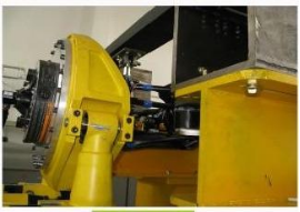
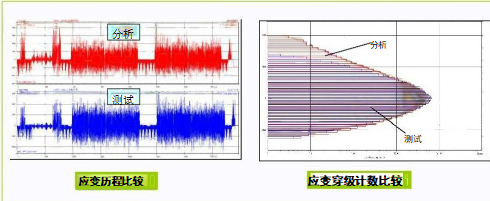
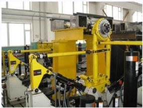 8通道随机载荷谱台架试验
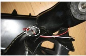
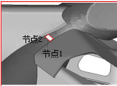
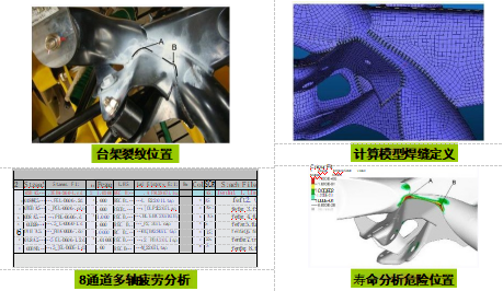
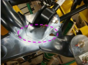 台架试验裂纹位置