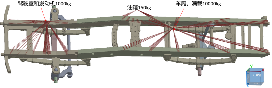
ABAQUS VS MeshFree应力-应变比对

Abstract.
The paper presents the results of the numerical study of the stress-strain state on the example of the detail “stand”, which is a bearing element of the pneumatic mechanis m design. The numerical modelling is carried out on the basis of difference approximation of the solution of partial differential equations. Some aspects of the theory of difference schemes are considered and approaches to the study of the complex stress state of the real structure are proposed by means of the finite element method and the finite difference method, by means of which approximate solutions can be obtained. The description of the behaviour of the studied element in these methods is carried out in the mesh domain using a set of selected stress and displacement functions. The relations between them are written in one of three main types-stiffness and ductility equations or mixed relations between forces and displacements, satisfying the conditions of continuity of the described properties of the element. It should be noted that both methods require the construction and solution of systems of algebraic equations. Numerical algorithms of approximate solution of differential equations of elasticity theory are implemented in software packages Abaqus (FEM) and Midas MeshFree (meshless method) when modelling the stress-strain state of the detail “stand”. A comparative an alysis and accuracy assess ment of the results obtained are given.
Keywords:
Stress Strain Finite-element model Finite-difference model Approximation
1 Introduction
An important task in determining the strength characteristics of any technical structure is the study of the stress-strain state of its elements due to the external influence of volumet-ric and surface forces, the identification of dangerous sections and local zones of stress concentration, the influence of environmental conditions, etc. The totality of the influenc-ing factors requires the construction of a mathematical model with the formalization of its behaviour, adequate to the operating process of a full-scale structure. At present, this approach is successfully implemented in the development of new engineering products at the design stage, including aircraft construction.
The mathematical description of the stress-strain state of a structural element is car-ried out using systems of differential, integral and integro-differential equations, the an alytical solutions of which are rarely obtained. Nowadays, one of the main tools for studying strength characteristics is detailed mathematical modelling using computer equipment and technologies. Modern software systems implement calculation algo-rithms based on numerical methods of solving systems of equations, for example, the theory of elasticity. The most common method of numerical calculation of the strength of structures is the finite element method (FEM), the programme implementation of which is carried out in modern engineering an alysis complexes, for example, Ansys, Abaqus and others. In many cases, specialists also use the finite difference method (FDM). The basis of applied numerical methods are, as a rule, solutions of systems of difference quotient equations in the form

here y and f are unknown and given functions from an integer argument. The fundamental solution to (1)is

The existing deep ana logy between the difference equation and the ordinary differ-ential equation with constant coefficients has become widespread in the construction of discrete mathematical models linking functions, integrals and derivatives. The replace-ment of continuous mathematical models by their discrete a nalogues in approximation theory requires the ability to preserve the required order of approximation of a continuous model by its discrete representation and to an alyze the degree of accuracy of this rep-resentation. The numerical methods developed have now gained significant advantages in solving engineering and technological problems in the creation of new high-quality equipment.
Many works, such as [1–6], have been devoted to the construction of computa-tional algorithms for solving problems in mechanics and their software implementation. However, it should be noted that numerical solutions of differential equations are based on mesh, variational and projection-difference methods, which allow to obtain either approximate values of the solution on some set of points, or approximate decomposition of the solution on some system of basis functions [7]. This article is devoted to the a nalysis of the application of the numerical study of the stress-strain state of a technical structure, implemented in the software packages Abaqus (FEM) and Midas MeshFree (meshless method).
1.1 Methods and Approaches
The Abaqus software package is widely used by specialists in the field of finite element strength calculations of engineering structures. It is based on the finite element method. Midas MeshFree, on the other hand, is a technology that allows accurate a nalysis without the need to create meshes, and is based on the finite difference method. These packages implement a matrix formulation of the discrete problem.
In the finite difference method, the differential equations are approximated by dis-crete values of quantities defined at selected points. In the finite element method, the structure as a whole (continuous medium) is modelled by dividing it into finite elements (regions), in each of which the behaviour of the medium is described by a separate set of selected stress and displacement functions. These sets of functions are defined in such a way that they satisfy the continuity conditions for the properties they describe [8]. Both methods require the construction and solution of a system of algebraic equations, which are not always of simple form.
In FEM, the behaviour of an element is described in terms of force and displacement components. To construct the mathematical model, the stress state is represented by generalised forces at the element nodes, and the displacements of the node points are represented by degrees of freedom. The relationships between forces and displacements of a finite element are written in one of three main forms [8]: stiffness Eq. (3), ductility Eq. (4), mixed relations between forces and displacements (5)
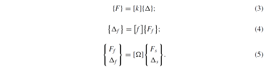
here {F}, {Ff}, {Fs} – vectors: forces, nodal forces, components of nodal forces related to fixation conditions; {Δ}, {Δf }, {Δs} – displacement vectors, nodal displacements from nodal forces, reactive displacements; [k], [ f ], [Ω] – matrices: stiffness, pliability of the element (area), transfer form between forces and displacements.
This approach is also valid for the FDM, where finite differences at the considered points (nodes) are compiled. The direct method of constructing relations for an element or region considers three systems of equations from elasticity theory: equilibrium equations, displacement / deformation relations, and equations of state. This method is particularly useful for elucidating the fundamental relationships between the finite element or finite difference approximation and the real structure.
Assuming elastic behaviour of the element, the relationship between stresses and strains is described by the matrix relation

Here {σ}, {ε} – vector-columns of stresses and strains; {σ0}, {ε0} – vector-columns of initial or residual stresses and strains; [D] – elasticity matrix characterising material properties.
In many cases, the components of the residual stress-strain state of the element, caused for example by technological effects, are not included in the calculations. The stress and strain components are determined from the known relations of elasticity theory. For the sake of brevity, these relations are not given.
The above relations are successfully implemented in calculation blocks in modern software packages by constructing a mesh model and loading it in approximation to real acting loads. However, one of the main problems of this method is the procedure of constructing a qualitative mesh, which is largely determined not only by the complexity of the geometric shape of the investigated structure, but also by the acquired skills of the performers. In other words, it depends on objective and subjective factors. For example, the displacements of any point inside the element e with nodes i, j, m are given by the column vector
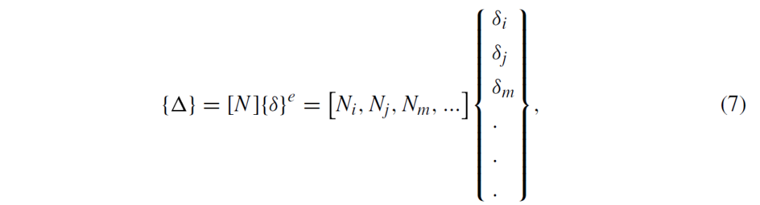
where [N] – shape function matrix, whose components Ni, Nj, Nm are position functions;  – vector-column of nodal displacements of the element е.
In order to meet the convergence conditions of the calculation process, certain requirements are placed on the shape functions, which cannot always be met. Difficul-ties in meeting the continuity condition arise in the selection of element displacement functions that ensure continuity along the entire boundary of the element with adjacent elements. Discontinuity of displacements at node boundaries in mesh construction leads to infinite deformations [9]. In addition, the process of mesh construction can be more labor intensive and time consuming than obtaining a numerical solution to the problem under consideration. It should be noted that in the case of large deformations, the dis-tortion of meshes during the calculation process is inadmissible, as the adequacy of the obtained calculation results is questionable.
At present, many specialists refuse to construct mesh computing algorithms and therefore develop meshless research methods and technologies for their implementation [10–14]. Such methods have found wide application in solving physical and mechanical problems about the motion of a material continuum, for example in hydromechanics. The modelling is performed by studying the interactions of conditional particles, for which an integral or other mathematical procedure is defined to reconstruct the fields of physical parameters of the continuum from the current state of a set of particles.
Let us consider the possibilities of applying the meshless method to the problems of studying the stress-strain state of loaded structures, where the elastic and plastic deformations can take both s mall and large values.
2 Basic Relations of the Numerical Solution of the Problem
The mathematical modeling of finite element an alysis of a structure is implemented in two ways. One involves solving differential equations describing the behaviour of an arbitrary infinitesimal domain. The other approach postulates a variational extremum principle valid for the whole domain [9]. And although these approaches are mathemat-ically equivalent, the ways in which they obtain approximate solutions are different. In the first approach, differential equations are approximated by of difference quotient. The second approach is related to the approximate minimization of the functional.
Consider the following differential problem. Suppose there is a differential problem in region D with boundary Г.

with boundary condition

here L and l – differential operators; f and φ – specified elements; u – the sought element of some linear normalized spaces F, Φ and U respectively.
If one of the variables is time t, the most commonly considered regions are of the form

where t – time; x – set of spatial coordinates, x = (x1, x2,…, xn).
The solution is sought in the spatial domain d (х) on the segment [x0, T] with initial conditions t = t0 (Cauchy problem), or in boundary and mixed problems, where the boundary conditions are set at the boundary Г(х) of the domain d (х).
The difference method is often used to solve differential problems. All derivatives contained in the equations and boundary conditions are replaced by approximating with finite differences. A mesh is defined in the solution – a finite set of points (nodes)

belonging to the domain

where h – mesh parameter; h – mesh spacing.
The approximate solution of the differential problem (9) and (10) is determined by the solution of the difference scheme uh, which depends on the parameter h. As a result, the differential operators L and l are replaced by difference Lh and lh.

In the solution of a linear boundary value problem

with boundary conditions of the form

the difference scheme of the differential problem on a uniform mesh Dh has the form

which is a system of algebraic equations of tridiagonal form

here p(x), q(x), f (x) ∈ D [a, b] – specified functions; A and B – specified numbers.
In the finite element method, the discrimination domain corresponds to the physical domain under investigation. In the meshless method, the study area D s extended, thus obtaining an artificially created computational domain with simpler geometry. The dis-crimination process is carried out by means of a structured mesh Dh, for which in many cases it is convenient to use a Cartesian mesh, Fig. 1.
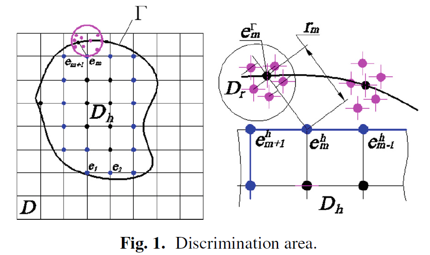
The boundary of the physical domain Г under consideration divides the extended domain D into an inner structured regular subdomain Dh and an outer subdomain. In the inner part, the approximate calculation of the linear integral I( f )ofthe form

is performed using linear quadrature formulas of the following form

where р(х) – weighting function; ci–quadrature coefficients; xi–quadrature nodes.
Various mathematical methods can be used to compute integrals in the outer sub-domain, such as the method in which the variables are not correlated with the nodes (Lagrange’s indeterminate multipliers method) or the weighted discontinuities method. In the weighted discontinuities method, the choice of weighting functions determines the solution scheme in the following classical ways [9]:
Collocation at a point
Collocation in the sub-area
Method of Galerkin
Finite cell methods can also be used to represent higher order boundaries and for numerical integration [14].
Modelling the stress-strain state of a structure of complex geometry using meshless method allows us to numerically solve a system of partial differential equations based on their approximation at arbitrary nodes. One such method is the finite point method. The essence of the method is shown in Fig. 1. For any selected edge point of the 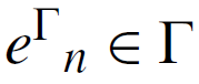 region D, a local point cloud Dr is constructed. The approximation is computed as a linear combination of the unknown nodal values of the cloud and certain metric coefficients. The distances between the nodal elements and the scattered points are minimized. Since rm is a function of coordinates, the value of the function ϕ at a contour point depends on the choice of shape function. Or [9].
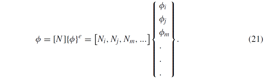
In the Dr cloud, the problem is solved by applying multiple fixed least-squares (MFLS). The discrete variant of this method consists in determining the unknown coef-ficients a1,…, am, which should ensure the minimum of the sum of the squares of the non-variance values ε of the function u (x) in a given set of points u1(x1), …, un(xn), ui(xi) ∈ 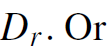

The unknown coefficients are found by solving a system of m linear equations. A detailed presentation of this problem is given in [15]. The authors believe that the advantage of meshless method are best realized through point collocation methods.
3 Modelling the Stress-Strain State of a Structure in Abaqus and Midas MeshFree Software Packages
The study of the stress-strain state is carried out using the example of the detail “stand”, the design of which is shown schematically in Fig. 2 (a).
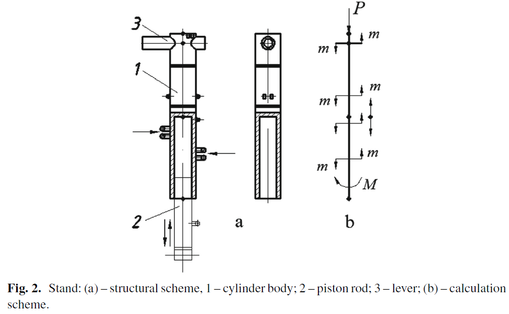
The investigated part is a bearing structure of the pneumatic gear, has a tubular branched structure and consists of a cylinder body and a lever. On the body of the part there are lugs for attaching other units of the mechanis m. The structure is made up of separate metal blocks joined together by welding. Under the action of an external load P, the body is lowered down the piston rod to the stop of the locking device. When the load is removed, the body returns to its initial position.
As a computational model we take a rod system with respect to the location of the internal cavity, Fig. 2 (b). During loading, the beam is subjected to compression, torsion and bending. The arm axis is subjected to joint bending in two perpendicular directions.
The study of the stress-strain state of the pneumatic gear is carried out using the software packages Abaqus (FEM) and Midas MeshFree (meshless method).
3.1 Finite Element Model in Abaqus Software Package
The constructed finite element model of the detail “stand”contains 43269 finite elements and 31557 nodes. The number of quadrangular 2D FEs is 33591 and the number of triangular 2D FEs is 2492. The ratio of triangular to quadrangular FEs is less than 0.08%. The finite element model and the mesh convergence plot are shown in Fig. 3.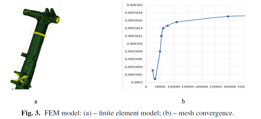
3.2 Model in Midas MeshFree Software Package
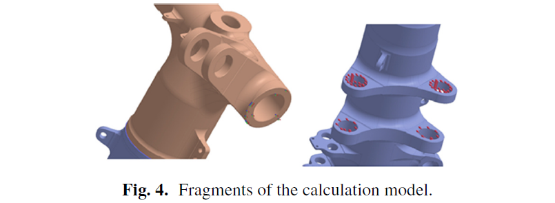
The construction of the model in the mesh domain was performed on the original geome-try, Fig. 4. The distribution of computational nodes is characterized by the mesh density. The degree of mesh density is medium to high. The change in mesh density is dictated by the need to obtain more accurate data on the structure’s stress-strain state in dangerous sections or the most heavily loaded segments. The construction of a qualitative mesh is not required in this method, which leads to a significant reduction in the labor intensity of the problem modelling. The method does not require verification of mesh convergence.
3.3 Modelling and Comparison of Results
The models were loaded according to the design scheme with absolute identity. For example, in the lever arm, the force was applied to the earrings along the two axes of the global coordinate system. The boundary conditions were set by restricting all degrees of freedom of the surfaces of the upper part of the lever arm. Figure 5 shows the results of the stress study of the two models. The physical and mechanical properties of the material were within the parameters of a medium carbon alloy steel. For the sake of brevity, they are not shown here.
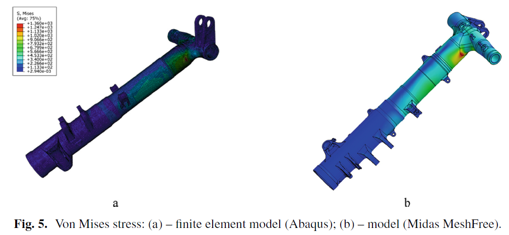
The results were compared based on visual an alysis of the color distribution zones for the two models and quantitative a nalysis of the point stress values. Five stress values were taken at selected points with the same coordinates in different diametrical directions. Some of the results are summarised in Table 1.
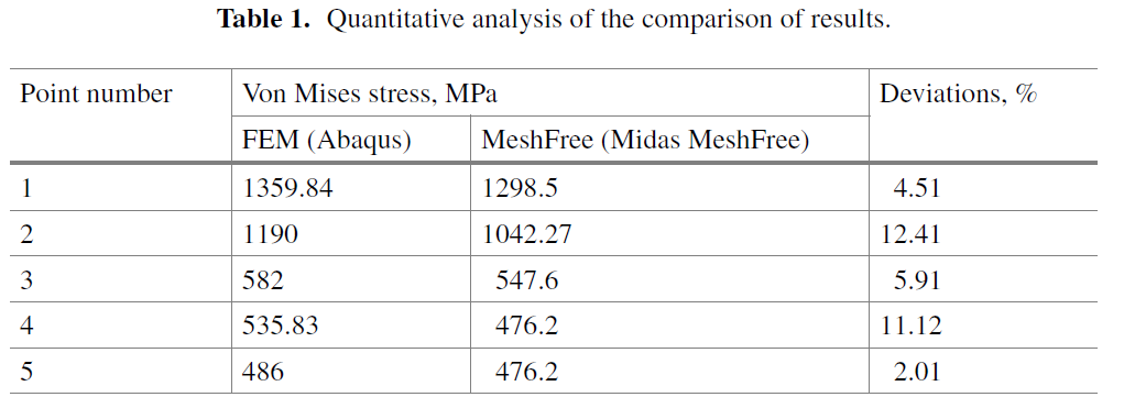
The quantitative an alysis carried out showed that the convergence of the results is quite close, except for the maximum error of 12.4%. This error can be related to the distortion of the mesh element in the zone of complex geometry, which requires additional refinement.
4 Conclusion
The research results obtained allow us to conclude that meshless methods of numerical investigation of physical processes are quite applicable to the structural an alysis of machine parts in order to justify their strength and reliability. With further study of meshless methods and their programming, new problems can be solved not only for modelling the motion of particles in a continuous medium. These methods allow, with accuracy acceptable in engineering practice, the study of the statics and dynamics of loaded solid bodies.
The main advantage of meshless methods in comparison with FEM is the reduction in the amount of work required to create a computational model that does not require the construction of a high-quality finite element mesh, as well as the absence of the problem of unrealistically obtained parameters in complex areas of the studied object’s geometry.
References
1.Cook RD, Milkus DS, Plesha ME, Witt RJ (2002) Concepts and applications of finite element an alysis, 4th edn. John Wiley & Sons. Inc., University of Winconsic
2.Lu K, Coombs WM, Augarde CE, Hu Z (2019) An implicit boundary finite element method with extension to frictional sliding boundary conditions and elasto-plastic a nalyses. J Comput Methods Appl Mech Eng. https://doi.org/10.1016/j.cma.2019.112620
3.Zhang H, Sun Y, Li C, Wang H (2020) Optimal design of the sealing structure of a hydraulic cylinder on the basis of a surrogate model. J Adv Mater Sci Eng 4:1–9. https://doi.org/10. 1155/2020/1753964
4.Dmitriev V, Danilin A, Popova A, Pshenichnova N (2022) Numerical a nalysis of deforma-tion characteristics of elastic inhomogeneous rotational shells at arbitrary displacements and rotation angles. J Computation 10(184):11
5.Kondratenko LA, Mironova LI (2022) Residual stresses under radial deformation of steel pipes. J Mach Manuf Reliab 51(7):630–636. https://doi.org/10.3103/S1052618822070093
6.Kondratenko LA, Mironova LI (2023) A generalized linear mathematical model of cutting part movement in deep hole machining. J Mach Manuf Reliab 52(8):843–852
7.Bahvalov NS, Kornev AA, Chizhonkov EV (2016) Numerical methods for solving problems and exercises. Laboratoriya znanij, Moscow
8.Gallagher RH (1975) Finite element an alysis. Fundamentals. Prentice-Hall, INC., Englewood Clifs, New Jersey
9.Zienkiewicz OC (1977) The finite element method in engineering science. McGraw-Hill, London, New York
10.Orate E, Idelsohn S, Zienkiewicz OC, Taylor RL (1996) A finite point method in computational mechanics. applications to convective transport and fluid flow. Int J Numer Meth Eng 39:3839– 3866
11.Löhner R, Oñate E (1998) An advancing front point generation technique. Commun Numer Methods Eng 14(12):1097–1108
12.Afshar MH, Naisipour M, Amani J (2011) Node moving adaptive refinement strategy for planar elasticity problems using discrete least squares meshless method. J Finite Elements A nal Des 47:1315–1325
13.Ortega E, Oñate E, Idelsohn SR, Flores R (2014) Application of the finite point method to high-Reynolds number compressible flow problems. Int J Numer Meth Fluids 74(10):732–748. https://doi.org/10.1002/fld.3871
14.Ma J, Ding W, Lin Y et al (2023) A fast and efficient particle packing generation algorithm with controllable gradation for discontinuous deformation an alysis. Geomech Geophys Geo-energ Geo-resour. https://doi.org/10.1007/s40948-023-00637-w
15.Oñate E, Idelsohn S, Zienkiewicz OC, Taylor RL (1996) A finite point method for an alysis of fluid mechanics problems. Comput Methods Appl Mech Eng 39(2):3839–3866. https://doi. org/10.1002/(SICI)1097-0207(19961130)39:22%3c3839
Author:
From:

https://doi.org/10.1007/978-3-032-04273-6_16