AQWA Workbench 12.0 版本的官方帮助文档

摘要:
本文是 ANSYS AQWA Workbench 12.0 官方帮助文档,介绍 AQWAWB 图形化界面的操作与建模规范。文档说明软件基于 DesignModeler 几何建模,支持面 / 线 / 点质量、点浮力、圆盘单元,提供自动网格划分与局部加密功能。核心支持水动力绕射分析,可设置重力、波向、波频与结构选择,输出静水力、响应幅值算子(RAO)、压力与运动结果。文档给出传统 AQWA 命令与 WB 树对象的对照,明确建模规则、单元限制、结果查看与动画导出方法,为海洋结构物初期水动力仿真提供标准化操作指南。
ANSYS AQWAWB Help
Copyright and Trademark Information
© 2009 SAS IP, Inc. All rights reserved. Unauthorized use, distribution or duplication is prohibited.
ANSYS, ANSYS Workbench, Ansoft, AUTODYN, EKM, Engineering Knowledge Manager, CFX, FLUENT, HFSS and any and all ANSYS, Inc. brand, product, service and feature names, logos and slogans are registered trademarks or trademarks of ANSYS, Inc. or its subsidiaries in the United States or other countries. ICEM CFD is a trademark used by ANSYS, Inc. under license. CFX is a trademark of Sony Corporation in Japan. All other brand, product, service and feature names or trademarks are the property of their respective owners.
Disclaimer Notice
THIS ANSYS SOFTWARE PRODUCT AND PROGRAM DOCUMENTATION INCLUDE TRADE SECRETS AND ARE CONFIDENTIAL AND PROPRIETARY PRODUCTS OF ANSYS, INC., ITS SUBSIDIARIES, OR LICENSORS. The software products and document- ation are furnished by ANSYS, Inc., its subsidiaries, or affiliates under a software license agreement that contains pro-visions concerning non-disclosure, copying, length and nature of use, compliance with exporting laws, warranties, disclaimers, limitations of liability, and remedies, and other provisions. The software products and documentation may be used, disclosed, transferred, or copied only in accordance with the terms and conditions of that software license agreement.
ANSYS, Inc. is certified to ISO 9001:2008.
U.S. Government Rights
For U.S. Government users, except as specifically granted by the ANSYS, Inc. software license agreement, the use, du- plication, or disclosure by the United States Government is subject to restrictions stated in the ANSYS, Inc. software license agreement and FAR 12.212 (for non-DOD licenses).
Third-Party Software
See the legal information in the product help files for the complete Legal Notice for ANSYS proprietary software and third-party software. If you are unable to access the Legal Notice, please contact ANSYS, Inc.
Published in the U.S.A.
AQWAWB Introduction
AQWAWB is a graphical interface for AQWA. It is used to create an element based model from geometry
defined in Design Modeler format, apply AQWA specific input and view results. The layout is similar to other Workbench based applications (e.g. Mechanical) and comprises a number of objects in a tree based layout.
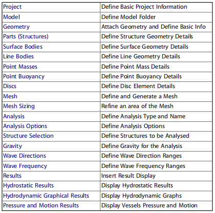
For a description of a particular tree object, select a link from below. If you are an existing AQWA user, then you may also find the "Information for existing AQWA users" (p. 3) a useful comparison of capabilities and definition methodology.
Each item in the tree is a command object, the properties of these are used to control the an alysis and view the results, each type has a different function and their abilities are described here. Most of these tree objects can be selected and then the right mouse button used to modify common functions, also this button can be used to add additional objects, such as masses or result views. Alternatively the dynamic toolbar can be used for adding additional objects.
There are a number of additional buttons that also control the view.
Table 1 Definition of tree objects
Information for existing AQWA users
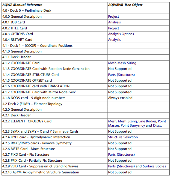
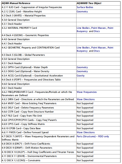
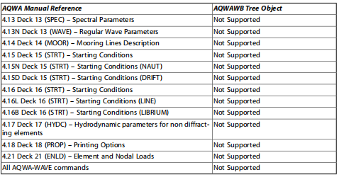
If you are familiar with the AQWA data files and help system, then you can use this section to find where an existing command is located in the AQWAWB tree objects.
Table 1 Cross reference of tree objects with AQWA commands
General modelling requirements
DesignModeler is the tool used for creating geometry for AQWAWB, for importing geometry created in
DesignModeler, see the Geometry section. When using DesignModeler to define the geometry there are a number of aspects that you should consider to ensure that your model is suitable for an alysis with AQWA, such as:
Ensure that the model is split at the water line, import or create each structure and then use a plane to split the surface bodies at the water level
When using lines to create beams, only tubular sections are supported in AQWAWB, all other sections will result in a stub element being formed and you will need to define additional information in AQWAWB
Each vessel / structure should be a part, so all the bodies that you have should be grouped via the multibody part facility. Note, there is not the possibility to rename these within AQWAWB
AQWAWB Interface Overview
AQWAWB follows the conventions used in other ANSYS Workbench products where it is appropriate for
AQWA. The user interface has a number of key areas, but is tree driven. Along with the tree and it's details pane are toolbars and graphical / text display windows
The toolbar uses a number of standard Workbench icons along with a number of specialist AQWAWB additions.
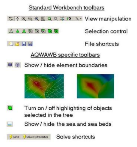
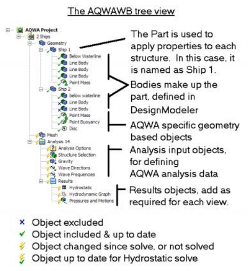
The tree and the details are where the objects that are used to define the modelling requirements are or- ganised. Depending upon the selection in the tree, a detail pane, normally located below the tree will show the details of the selected object.
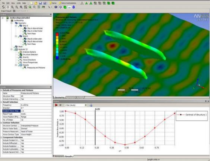
There is either one or two other windows shown, depending upon the state of the an alysis or tree item that is selected, firstly the main window, this generally shows the model (either geometry or mesh views) and, if you are viewing Hydrostatics results, the properties tab is enabled for text based results. The secondary window is used for displaying messages, control the results and displaying graphs. This will appear automat- ically, depending upon the tree item selected.
Project
Use this to enter in custom information about the author and any references or description for this an alysis. Information about the creation date of the file and when it was last modified is also automatically saved. This data is also written to the an alysis data file for later reference and the project name is used.
Model
There is the option to change the model name for easier reference. It is used to name a folder in which the subsequent an alyses will be stored.
If this is unchanged, when a geometry is attached the model name defaults to be that of the geometry.
Geometry
When selected a Design Modeler geometry database (.agdb) can be attached to the model. Design Modeler can be used to either create your model geometry or to import / link to existing CAD based geometry. When attaching geometry (using the context menu or toolbar), each part becomes a separate structure in AQWA.
If a structure is to be formed of both diffracting and non-diffracting elements, these should be in separate defined bodies within the (multi-body) part.
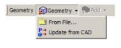
When attaching geometry the Model name is automatically changed to be that of the geometry, the an alysis is stored in a folder under the model name. The units also change to be those of the model; these can be modified via the units menu if desired.
AQWAWB assumes that the still water surface parallel to the XY plane and Z is positive up.
All structures are located in a global a nalysis space; note that Hydrostatic Results (p. 20) and Hydrodynamic Graphical Results (p. 21) are also presented in global directions.
Within the geometry you can select the types of bodies that will be attached.
Once attached the diffracting behaviour of surface geometry can be selected, lines can be set to be Tubular (TUBE Elements) or Slender Tube (STUB elements) and additional AQWA specific objects can be added, such as Point Masses (p. 16), Point Buoyancy (p. 16) and Disc (p. 16).
The sea geometry’s water level, depth and size can be used to alter the graphical view. The sea level must coincide with where surface geometry is split to form above water (non-diffracting) and below water (dif-fracting) sections. If this is set before attaching a geometry file, surfaces with centroid below this level will automatically be set to diffracting and those above non-diffracting. You can manually change bodies to be non-diffracting or diffracting.
Modification to the water level will affect the ZLWL keyword in the AQWA data file. The water depth can also be set, as well as modifying the graphical display, this will set the depth of water for the an alysis via the DPTH keyword in the AQWA data file.
The density of the water can also be changed; this will affect the DENS keyword in the AQWA data file. Note: It is not yet possible to employ symmetry in AQWAWB, hence the full model must be meshed.
Parts
A part is used to group the objects that form a ship or other structure that is to be ana lysed in AQWA in the Structure Selection (p. 18), each part will be assigned a structure number for the an alysis. The name is read in from the geometry database and the graphical view will show the part; the appropriate structure will be highlighted when the part in the tree is selected.
To help visualisation, it is possible to show or hide specific parts using the Part Visibility option. The Part Activity option is used to decide what structures are used in the an alysis.
By default the structure is set to be free to move. Alternatively, the whole structure can be fixed using the "Structure is fixed in place" option, in which case a FIXD keyword is used.
If an automatically generated internal lid (ILID AUTO) is required to prevent irregular frequency problems,
then this can be selected here and it will be automatically generated during the AQWA an alysis. If you have a structure with a moon pool where an automatic internal lid is not suitable, then you can form an external lid using a Surface Bodies (p. 15) with the abstract geometry option.
Coefficients for additional linear, frequency independent damping about the global X and Y axes can be
input. For a vessel modelled conventionally with its longitudinal axis in the global X direction, RX will corres- pond to roll.
These data items are strictly the 4,4 and 5,5 terms in the linear damping matrix, and are equivalent to the 4th and 5th coefficients on the FIDD card in AQWA.
Use the context (right click) menu or the toolbars to add or remove additional AQWA specific elements into the geometry, such as: Point Masses (p. 16), Point Buoyancy (p. 16) and Disc (p. 16).
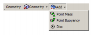
A full list of the types of bodies is:
Surface Bodies
Line Bodies
Point Masses
Point Buoyancy
Disc
Surface Bodies
Surface bodies are areas that can be meshed to create diffracting or non-diffracting elements for the AQWA an alysis. The name of the surface body will be obtained from that given in Design Modeler and it cannot be changed here.
If a body is not required for the an alysis it can be suppressed. Suppressed bodies will not be meshed and will be excluded from the an alysis.
It is possible to change the type of surface from being a physical definition to an abstract definition, if it is to be physical geometry then there is an option to set it to form either diffracting (TPPL DIFF or QPPL DIFF) or non-diffracting (TPPL or QPPL) elements for the a nalysis.
For abstract geometry, a number of options are available to select how this geometry is to be used. If an area is of particular interest, then the Custom Results Positions option enables a mesh to be applied and each node of the mesh will form a field point (FPNT) element, additional information will be available at these points. Alternatively internal and external lids can be created to suppress standing waves either
between structures or within structures. Once meshed, these will form the basis for the ILID or VLID data.
Note, automatic internal lids can be selected using the Parts (p. 14) options.
If the generation of an external lid is chosen, two additional parameters are required. The first is a damping factor between 0 and 1. The factor represents how effective the lid is to be, 0 will result in no reduction in velocity and 1 will prevent any vertical velocity under the lid.
The second parameter is termed the Gap. It is a representative size for the lid; typically the distance between the two vessels or the width of a moon-pool. It enables the lid properties to be tuned to the resonant fre-quency of waves in the gap
Line Bodies
Line bodies are used to create single elements for AQWA, how they are interpreted depends upon the cross section of the line; if it has a circular cross section, then it will be automatically converted into a tubular line and will create standard tubular (TUBE) elements, all other sections will create slender tube (STUB) elements. The content of the details pane changes considerably depending upon the type of line, the details are dis-cussed below.
Line type: Tubular
If the line in Design Modeler was defined with a tubular section, the line body will default to this setting;
the tube diameter and thickness are automatically read from the Design Modeler data, along with the calcu- lated inertia values.
In this case there are options to have both of the ends of the tube sealed, this is the default and in this case the tube would be buoyant, however, the tube does not have longitudinal drag or added mass unless discs are created at the ends. Discs can automatically be applied at either or both ends with the Tube End Closure option, in this scenario, default disc parameters are used, if you require different parameters, discs can be excluded here and added manually.
Viscous drag and added mass coefficients can be defined and will be written to the data file, although drag is not used in hydrodynamic or hydrostatic ana lyses (AQWA-LINE). A density of the tube is also required; this defaults to the standard value for steel.
Line type: Stub
For all sections other than tubular, only the inertias will be obtained automatically from the parameters that are entered in Design Modeler. If a stub element is not required, then it is possible to change it to a tubular line and define the diameter and thickness within AQWAWB.
If a stub element is chosen there are options to change the diameter in both the local Z and Y directions, as well as the cross sectional area. For AQWA valid cross sectional areas vary between an ellipse and a rect- angle with the width and height of the two diameters. It is also possible to define the mass contribution that the stub will contribute to the model.
Point Masses
Point mass (PMAS) elements can be inserted into the model; the properties can either be input manually or can be Program Controlled.
A manual point mass must have all its properties input by the user. Moments of inertia can be defined directly or by inputting radii of gyration.
If a program controlled point mass is used, the mass and the horizontal position will be calculated from the panel elements in the structure (i.e. excluding tubular stub lines and point buoyancy bodies). The mass will equal the mass of water displaced, and the horizontal position will be that of the centre of buoyancy. The moments of inertia (or radii of gyration) and vertical position cannot be determined by the program and must be input.
Tip: after inserting your point masses, insert a hydrodynamic diffraction ana lysis and solve for hydrostatics only, then the hydrostatic results will be available and the values of mass will be calculated before performing the full AQWA an alysis.
Point Buoyancy
Point buoyancy (PBOY) elements can be inserted into the model; these require a position and a volume.
Disc
Disc elements (DISC) can be used to create an area that has drag and added mass in the direction perpen- dicular to the disc. The diameter of the disc is required along with the centroid and the definition of the
normal direction. If the centroid is at the position of an existing vertex, then that can be selected, otherwise, direct entry of the co-ordinates is permitted. The normal can also be selected in this way.
The default values of the added mass and viscous drag coefficients can be modified if desired.
Note: drag is not used in hydrodynamic diffraction an alyses (AQWA-LINE).
Mesh
The mesh is automatically generated on the bodies in the model; its density is based on the defeaturing tolerance and max element size parameters.
These parameters apply to the whole structure, although parts or bodies of the structure can be suppressed to prevent un-necessary meshes being created. If suppressed, they will be excluded from the an alysis and subsequent result display.
The defeaturing tolerance controls how s mall details are treated by the mesh. If the detail is s maller than
this tolerance then a single element may span over it, otherwise the mesh size will be reduced in this area to ensure that the feature is meshed. The defeaturing tolerance can not be greater than 0.6 × max element size.
The maximum element size controls the maximum size of the element that will be generated. In AQWA this is explicitly related to the wave frequency and water depth, which can be set in the Geometry (p. 13); in
either case modification will cause the maximum element size to be adjusted accordingly.
If a s maller element size is required for a particular part or body, then one or many Mesh Sizing object(s) can be added to refine the mesh.
The Meshing Type option controls the algorithm that is used for the mesh generation, the default is for it
to be Program Controlled, in which case, the Surface Only Meshing algorithm is used for parts that only
contain surfaces and the Combined Meshing is used if the part also includes lines. If the Program Controlled option fails to produce a satisfactory mesh, then you may control the selection manually.
The larger the maximum element size, the less accurate the results. However, the AQWA solver is limited to 12000 elements, of which 8000 may be diffracting. The number of generated elements is reported, although these exclude any non-meshed elements (e.g. Discs).
Furthermore, if the size is set too large and defeaturing is also large, the meshing algorithm may generate single elements at the bow of a ship. This element arrangement is not permitted for AQWA.
Use the toolbar item or context menu to generate the mesh
画画
Note: It is not yet possible to employ symmetry in AQWAWB, hence the full model must be meshed.
Mesh Sizing
Adding a mesh sizing object enables the refinement of a mesh on a given part or body by enabling a
s maller element size to be associated to the geometry. Any number of sizing objects can be added to the tree as required.
An alysis
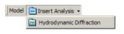
To perform an an alysis the specific an alysis type needs to be added, this can be achieved by selecting the model and then using the Insert An alysis button. At present only Hydrodynamic Diffraction (AQWA-LINE) an alyses are supported.
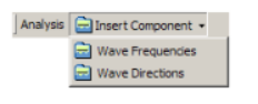
When a Hydrodynamic Diffraction an alysis is inserted, there are two ana lysis options, either to calculate the Hydrostatics only (AQWA stages 1 and 2) or to calculate the full Hydrodynamic results.
The an alysis name controls the name of the generated AQWA data files, for this reason it is limited to be 28 characters in length; you are able to change the name within the details panel.
The a nalysis name will automatically have a number following it; this causes the name to be unique for this session. The number prevents previous a nalyses being over-written; you will be warned if an an alysis of the given name exists.
For each Hydrodynamic Diffraction a nalysis, additional Wave Directions and Wave Frequency objects can
be added to the an alysis up to the maximum of one per structure. Checks will be carried out as part of the ana lysis to ensure that each structure has only one set of wave directions or wave frequencies applied.
Typically you will need to define input for the following tree items for an an alysis to be carried out:
A alysis Options
Structure Selection Gravity
Wave Directions
Wave Frequencies Results
An alysis Options
The a nalysis options object enables the modification of how the ana lysis runs and the results that are pro- duced.
The Sea Grid Size Factor controls how much larger the sea area is than the structure (or structure group, if there are interacting structures present). The default value of 2 will cause the sea area to be twice as long as the structure in the X or Y directions, a ratio of X = 1.6 Y is maintained.
Output File Options
These options control what is outputted to the AQWA output text file or to specific additional files, refer to the AQWA reference documentation for more details.
QTF Options
These options control the QTF output; refer to the AQWA reference documentation for more details.
Common An alysis Options
These options control how the a nalysis is performed and what action is taken in a number of instances; in normal circumstances they will not need adjusting, however, if you get modelling warnings then you may wish to turn on the "Ignore modelling rule violations" option, refer to the AQWA reference documentation for more details.
StructureSelection
The structure selection tree object enables the definition of interacting structures, along with any that you want to exclude for this particular a nalysis.
It also enables the order to be changed; the AQWA solver demands that a group of interacting structures
are consecutively ordered for the ana lysis. Refer to the AQWA documentation for more details of this require- ment.
Structures can be selected graphically (use CTRL key to select more than one) for inclusion in a group or to be excluded from the an alysis. If a structure is excluded, then it will automatically be removed from any
groups and the structure order, however, the selections in wave directions and frequencies will need to be updated explicitly.
Gravity
This tree object enables the definition of gravity for this an alysis; changes can be made if you want to try to match another an alysis.
Wave Directions
The wave directions tree object enables the definition of a range or single wave direction to use in the a nal ysis.
The wave directions can be applied to either a single or multiple structure selection; these are selected graphically and are highlighted in the view if the "Select Tree Related Items" is turned on.
If different wave directions are to be applied to different structures this can be achieved by selecting the
Ana lysis tree item and inserting additional wave direction objects. This will only be permitted if the structures are in different interacting groups.
The option to apply a structure forward speed is also included, if one is applied, then only a single wave direction can be ana lysed.
Waves are automatically created in -180 and +180 directions and then either the interval or the number of intermediate directions can be specified. If a direction range is of particular interest, additional ranges or
specific directions can be added.
Duplicated directions will automatically be removed; although the number of directions does not contribute greatly to the an alysis time, there is a limit imposed of a total of 41 directions for any one structure.
Note: It is not possible to employ symmetry in AQWAWB.
Wave Frequencies
The wave frequencies tree object enables the definition of a range or single wave frequency to use in the an alysis.
The wave frequencies can be applied to either a single or multiple structure selection; these are selected graphically and are highlighted in the view if the "Select Tree Related Items" is turned on.
If different wave frequencies are to be applied to different structures this can be achieved by selecting the An alysis tree item and inserting additional wave frequencies objects. This will only be permitted if the
structures are in different interacting groups.
Similarly to the wave directions, either a single or range of frequencies can be specified. The start frequency will default to 0.1 rad/s and the end frequency will default to that determined by the mesh. Frequenciescan be defined either by the frequency or by inputting a period, the maximum wave period (and equivalent frequency) permitted is 200s.
The intermediate positions can be defined either by a constant frequency or period, or by entering a numbe of values. If a number of intermediate values are chosen, they will be equally spaced depending upon the interval type.
Additional frequencies can be employed by specifying additional frequencies; any duplicate frequencies will be automatically removed. The number of frequencies chosen extends the solution time linearly.
and may need to be updated manually.
Results
Results can be added when this object is selected; this can be either before or after an an alysis is performed. This can be achieved by either adding an object via result toolbar or via the context (right click) menu.
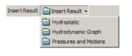
If the input to an an alysis is changed then the results objects will indicate that they are out of date via the yellow lightening bolt icon, however, if previous results exist, they will still be available until the an alysis is re-run.
The following types of results are available:
Hydrostatic Results
Hydrodynamic Graphical Results
Hydrodynamic Pressure and Motion Results
Hydrostatic Results
The hydrostatics results tree item enables you to view the centres of buoyancy, floatation and gravity in the graphical view once a hydrostatic or hydrodynamic solve has been performed.
Detailed hydrostatic results are available by selecting the Properties tab at the bottom of the graphical view. Results can be filtered by the selected structures. Any number of hydrostatic results can be added.
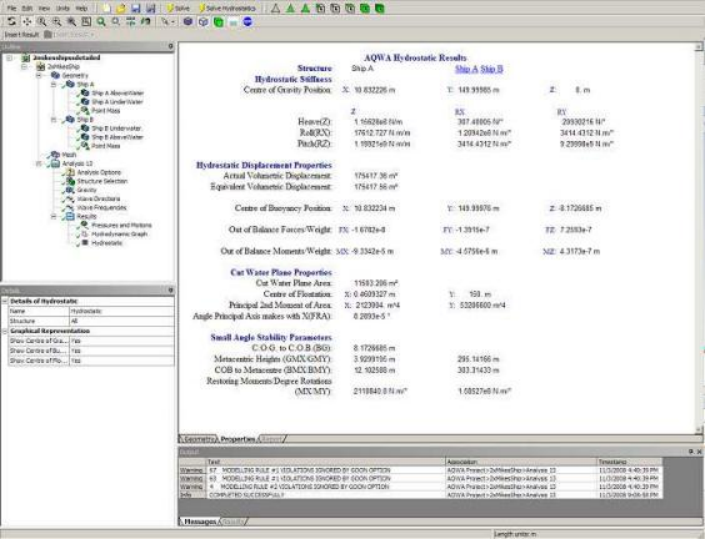
Note: for best graphical display of hydrostatic results changing the view option to Wireframe without Select Tree Related Items is recommended.
Hydrodynamic Graphical Results
The hydrodynamic graph object enables the plotting of up to 4 comparative graph results once a hydro-
dynamic solve has been performed. These results can be plotted against either Frequency or Period and can be either Amplitude or Phase based.
For each line to be plotted, select the required input to define the structure, results type and component and direction, if appropriate. The graph will appear automatically below the graphical view.
Any number of graph result objects can be added.
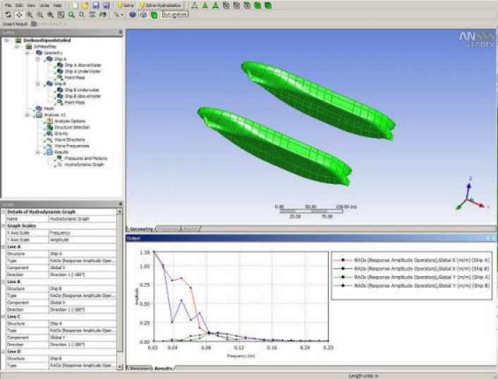
Note: AQWA always produces results in global co-ordinate systems; traditionally X direction is defined as being
along the ship’s length. However, if the user is aware of the results orientation, this does not have to be respected in Design Modeler.
Hydrodynamic Pressure and Motion Results
The pressure and motion results object enables the visualisation and display of a number of results generated from AQWA once a hydrodynamic solve has been performed. Any number of pressure and motion results may be added.
The structures to be shown under a particular set of results can be selected in the graphical view, by default all interacting structures will be shown, although this can be turned off via the Include Interacting Strs option.
The frequencies and directions available will be those that exist for all selected structures which were last successfully an alysed (hydrodynamic solve), or those currently specified if no an alysis has been undertaken. If a frequency or direction is selected and then on a subsequent an alysis not an alysed, then the option will default to the first available frequency or direction.
The Incident Wave Amplitude can be modified to provide results that are factored from the unit 1m wave that is the default, extreme modification may extend results beyond the capabilities of a linear an alysis, in which case inaccurate results can be produced.
The result presented can either be defined by the Cyclic option, where an equivalent phase position of the incident wave component can be selected (or is shown in the graph as the time as a proportion of wave
period if a range is chosen), or an Amplitude, result. Furthermore, the Minimum and Maximum values of the selected result can be displayed.
When Cyclic is selected, 0° (or t/T = 0) and 90° (or t/T = ¼) can be selected, along with the facility to enter
a specified phase position (in rotation units), or to create a range of results for animation. If a range of results is selected, then the number of steps can be selected. The more steps, the s moother the animation, but the
longer the results take to process.
If a particular result is required from the animated set, then the graph can be clicked upon to display. Other controls on the graph display enable the time over which the animation occurs to be altered and an avi
animation to be created.
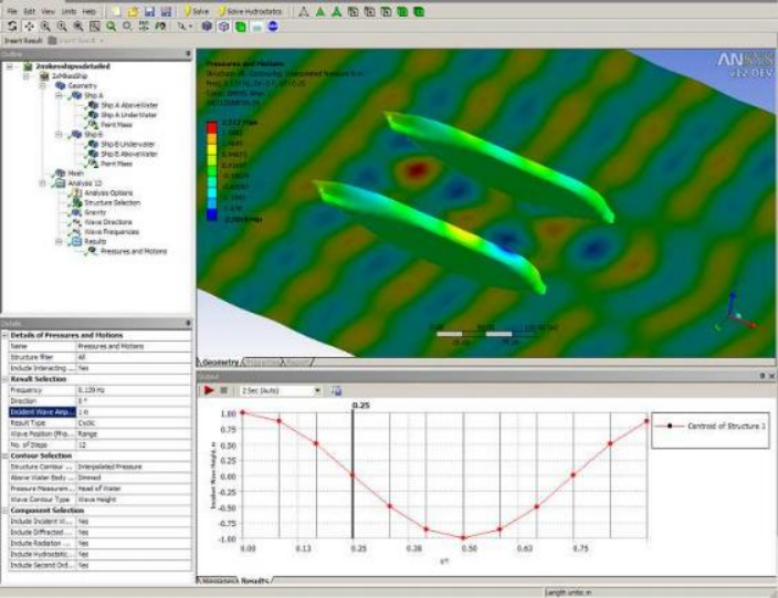
A number of results can be presented in this manner; by default the wave height and the interpolated
pressure are shown. It is only possible to plot wave contours when the structure contour type is compatible, for this to be achieved, the result must be plotted on nodes and must be a displacement type result. The
interpolated results are determined from the panel (element) pressures that are generated from AQWA.
Any combination of wave components can be enabled and disabled to enable visualisation and checking of the results.
The sea mesh size can be altered via the An alysis Options (p. 18), Sea Grid Size Factor setting. The sea mesh extends throughout the structure; however, the results that are presented within dry areas are not accurate.
免责声明:
本页面/内容部分素材来源于互联网公 开 信 息,旨在传递更多信息,不代表本平台立场。
版权归原作者或机构所有,如涉及侵权,请通过平台联系我们,我们将在核实后第一时间处理。
本平台对转载内容的真实性、准确性不作任何保证,用户需自行判断并承担使用风险。