NFX|叉车属具纸箱夹 Carton Clamp仿真分析

Abstract
Carton clamps and forklift attachments allow users to efficiently handle shipping units including unitized loads, large shipping cases, and crates without the need for pallets. As the use of palletless handling by clamp trucks increases, the need for simulation research on clamp truck handling also grows. This study defines an an alysis model for a segment of a heavyweight corrugated package (HCP) (L ×W× D = 1,003 × 980 × 1,880 mm, weight = 1,760 N). Finite element an alysis (FEA) evaluated the slippage of the HCP under various conditions, using a representative load. The FEA results indicated minimal change in slippage beyond a certain clamping pressure. The slippage was lowest when the rubber contact pad on the carton-clamp truck arm was trapezoidal. Additionally, the slippage of HCP was reduced by more than 50% when using double-wall corrugated paperboard compared to single-wall corrugated paperboard. Under the same conditions, the error between the minimum clamping pressure estimated by the improved minimum clamping pressure model and the pressure an alyzed through FEA was approximately 12%. Thus, if the physical properties used in FEA are enhanced, the FEA-based simulation technique can more accurately estimate the minimum clamping pressure during carton clamp truck handling.
Keywards
Heavyweight corrugated package; Carton-clamp truck; Minimum clamping pressure; Carton-clamp truck handling; Finite element an alysis
Introduction
A forklift truck, a typical handling machine, is suitable for handling pallet-based freight, whereas a carton-clamp truck can handle freight without using pallets. Carton-clamp trucks are highly efficient when used with other handling machines,such as push/pull with slip sheets. They increase space efficiency and reduce management costs in factories or warehouses[1-3]. As palletless handling by carton-clamp trucks expand across various industries, the need for computer simulations to optimize clamping pressure, the most crucial factor in cartonclamp truck handling, is increasing.
Stewart and Batt[4] developed PSD profiles for warehouse handling and truck loading using carton-clamp trucks to drive a clamping-force simulation device. Singh et al.[5]an alyzed relationships among ride height, measuring position, stacking patterns, shock intensity, load retention, and load containment in carton-clamp truck handling of unitized loads. They found that vibration levels in the 4-20 Hz range were much higher than those in transport systems like trucks or trains. Park et al.[6] modeled the appropriate clamping pressure, considering one-time handling weight and the actual contact area between the carton-clamp truck arm and packages by measuring the dynamic load factor and friction coefficient for handling a heavyweight corrugated package. Park et al.[7] also an alyzed the effects of payload, traveling speed, and tire type on vibration levels during carton-clamp truck handling, presenting their PSD profiles for three test courses: the test course designed based on a case study in the home appliance industry, ASTM D6055[8], and ISTA 3B[9]. The type of load generated during carton-clamp truck handling results from handling environmental conditions such as weight, clamping method,road conditions, and driving speed. Additionally, the load varies based on the package shape, packaging condition,packaging material, and the material and shape of the rubber contact pad on the carton-clamp truck arm.
Due to limitations in experimental methods, simulation techniques like finite element an alysis (FEA) are required.Therefore, in this study, we developed an FEA-based simulation technology for carton-clamp truck handling, using various data from previous studies[6,7,10,11]. We an alyzed factors affecting load slippage between clamp arms and the shape design factors of the rubber contact pad. Additionally, it compared test-based minimum clamping pressure with FEA results for carton-clamp truck handling.
Materials and Methods
1. An alysis range
In this study, to develop an FEA simulation technique for the load behavior of various variables in carton-clamp truck handling (Fig. 1)
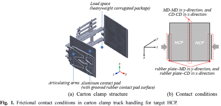
we first established a representative load that accurately considered the handling environmental conditions.The behavior of this load was a nalyzed based on the outerpackaging material, the shape of the rubber contact pad, and clamping pressure.
To determine the representative load, the composite PSD profile an alyzed by the research team during the handling process of the same target heavyweight corrugated package(HCP) (weight: 1,760 N, dimensions: L ×W×D=1,003×980×1,880mm) as in this study, was applied[7]. This composite PSD profile, which included all the PSD profiles measured for each combination of variables such as driving speed, road surface condition, and clamping method, allowed for the calculation of the representative load.
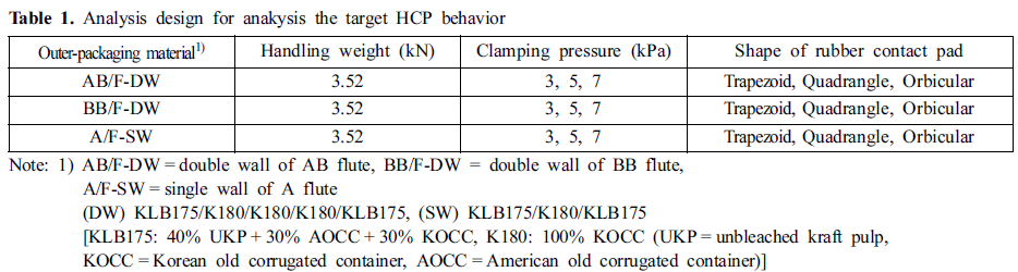
The target HCP behavior for this representative load was an alyzed for combinations of three types of outer-packaging material, three types of rubber contact pads on the cartonclamp truck arm, and three levels of clamping pressure, as shown in Table 1
The shape and dimensions of the rubber contact pad (Fig. 2) were determined through investigations by the manufacturer and the site of use. The clamping pressure range included the pressure normally applied in practice when handling two target HCPs, as shown in Fig. 1(b).

2. Definition of an alysis model and modeling
In Fig. 1(b), the s mall-volume element within the real contact area between the target HCP and the rubber contact pad of the carton-clamp truck arm is defined as the an alysis model (Fig. 3).
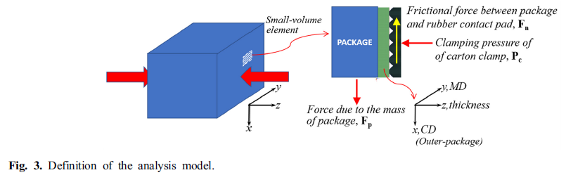
This element selection considered the left-right symmetry around the HCP in carton-clamp truck handling and the plane motion, with the center of gravity of the HCP confined to the xz plane, ignoring movement in the traveling direction (y).
The FEA assumptions for the an alysis model are as follows:
▖FEA an alyzes the behavior within a defined s mall volume element;
▖Target HCP, wrapped in a corrugated outer-packaging material, is considered a rigid body, and the kinetic conditions between the outer-packaging material of the HCP and the rubber contact pad are considered Coulomb friction;
▖Total weight of the target HCP is concentrated in the area of the rubber contact pad of the carton-clamp truck,resulting in frictional motion;
▖Due to the clamping pressure of the carton-clamp, only elastic deformation occurs between the friction materials,and an inelastic area is not considered.
The friction area of the an alysis model was 36 mm² (36×1mm), a fraction of the friction area of the entire model, which was 1,185,800 mm² (1,210 × 980 mm): (target HCP) L ×W×D = 1,003 × 980 × 1,880 mm, and (carton-clamp arm) 1,210 ×1,210 mm. The an alysis model for each combination of the three types of outer-packaging materials of the HCP and three types of rubber contact pads of the carton-clamp truck arm was expressed as an FE model, and midas NFX software was used for FE modeling[12]. Fig. 4 shows the modeling results for the rubber contact pad with the outer-packaging material BB/F as an example.
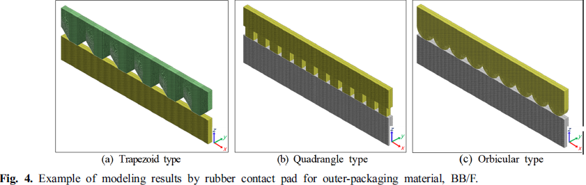
3. Load (traction) and boundary conditions, and an alysis methods
The clamping pressures applied in FEA were 3, 4, and 5kPa, equivalent to 3 ×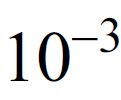 , 4 × , and 5 × N/mm in a two-dimensional model (1mm thick). The handling weight supported by the rubber contact pad of the an alysis model was determined based on the friction area ratio between the entire model and the an alysis model. Specifically:
▖Handling weight supported by the rubber contact pad on one arm: 1,760 N (half of the total handling weight of 3,520 N);
▖Friction area ratio between the an alysis model and the entire model: 3.04 ×  (36/1,185,800);
▖Handling weight supported by the rubber contact pad of the an alysis model: 0.0535 N (1,760 N × 3.04× ).
The slippage of the load during carton-clamp truck handling was significantly affected by vertical vibrations. However, Park et al.[6,7] found that vibration intensity during handling was significant not only vertically but also laterally. Therefore,in this study, the representative load was determined by summing the vibration magnitudes (overall rms G,[7]) in both directions to simulate extreme conditions for slippage.Specifically:
▖Overall rms G in the lateral direction: 1.01
▖Overall rms G in the vertical direction: 0.76 + 1 (Gravity)
▖ , Representative load: (0.0535/9.81)×2.0292G×9.81=0.1086 N
The FEA proceeds in two stages. First, the an alysis model is compressed with the clamping pressure Pc of the cartonclamp truck to generate friction force. Then, the dynamic load Fp from the mass of the HCP is applied to an alyze the relative displacement between the HCP and the rubber contact pad(Fig. 3).
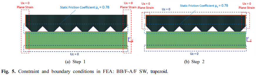
Fig. 5 shows the constraints and boundary conditions for Steps 1 and 2 of the FEA. In Step 1, the x-direction motion of the left and right sides of the rubber contact pad and the HCP,and the z-direction motion of the HCP bottom, were restrained. In Step 2, the x-direction motion of the left and
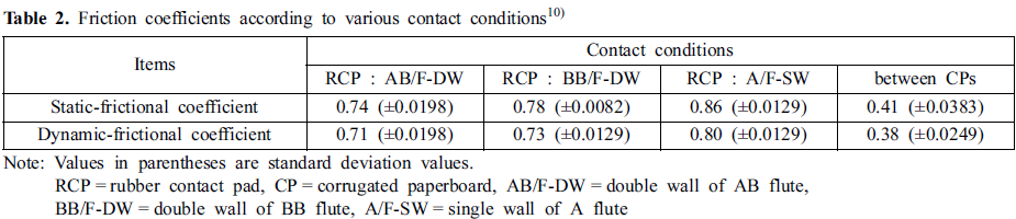
right sides of the rubber contact pad and the z-direction motion of the HCP bottom were restrained. The friction coefficient applied to the friction contact conditions in the FEA is based on Park et al.[10]. The friction coefficient between the rubber contact pad and the corrugated outer-packaging material varied with the flute type of the corrugated paperboard; thus, values for each flute type were applied. The friction coefficient between the corrugated paperboards was averaged across the machine direction (MD), cross-machine direction (CD), and flute type (Table 2)
4. Mechanical properties applied in FEA
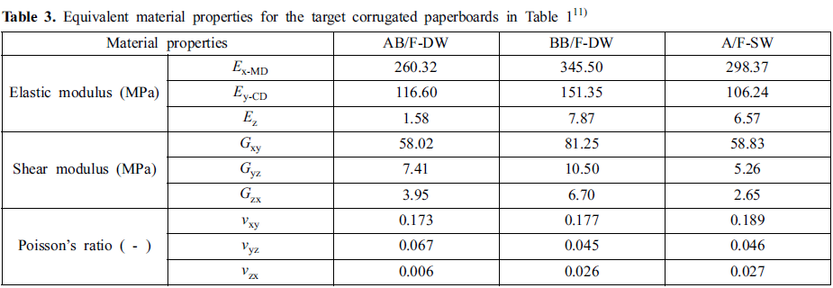
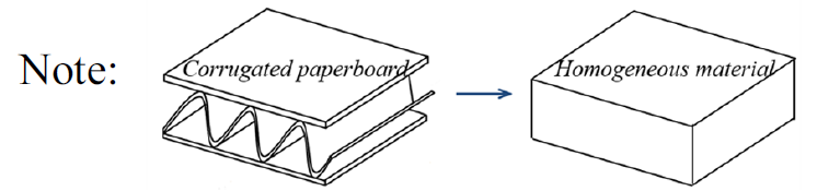
The outer-packaging material of the target HCP is corrugated paperboard. Due to its complex structure, considerable time and effort are required for FEA. Thus, this study used equivalent mechanical properties and simplified models for each type of corrugated paperboard reported by Park et al.[11].Only the mechanical properties needed for the 2D model were extracted from the equivalent properties of the 3D model in a previous study by Park et al.11) and are listed in Table 3
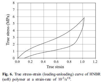
Similar to corrugated paperboard, applying rubber properties in FEA is challenging and significantly affects the results and processing time. This study used the properties of a hydrogenated nitrile butadiene rubber (HNBR) contact pad,determined using the Mooney–Rivlin model12) from the stress-strain relationship of a uniaxial tensile test (Fig. 6).
Results and Discussion
1. Package slippage due to clamping pressure and shape of the rubber contact pad
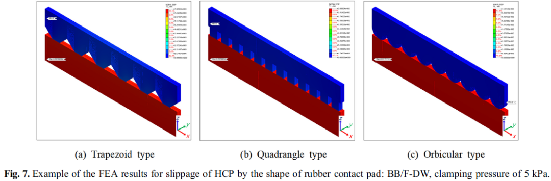
Based on the an alysis design in Table 1, the an alysis model was expressed as a FE model. FEA was performed considering the load, boundary conditions, and representative load according to the actual handling conditions of the cartonclamp truck. For example, Fig. 7 shows the FEA results for the slippage of the HCP when the outer-packaging material was BB/F-DW, and the clamping pressure was 5 kPa.
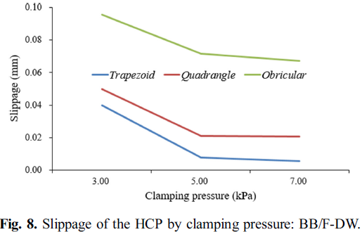
When the outer-packaging material was BB/F-DW, the slippage and relative displacement between the clamp arm and the HCP gradually decreased with increasing clamping pressure. However, after 5 kPa, the variation was minimal.Notably, the rubber contact pad's shape had the s mallest impact when it was quadrangular (Fig. 8).
The slippage of the HCP was largest with the orbicularshaped rubber contact pad and s mallest with the trapezoidal shape at the same clamping pressure (Fig. 9). The difference between the trapezoidal and quadrangular rubber contact pads was minimal compared to the orbicular shape. Therefore, the trapezoidal shape was considered the most suitable for the carton-clamp truck arm in this study.
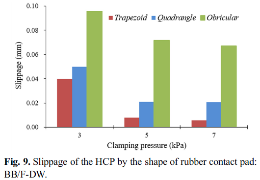
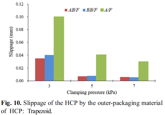
Fig. 10 shows the FEA results for the slippage of the HCP according to the type of outer-packaging material when the rubber contact pad was trapezoidal. The slippage of the HCP was significantly s maller with DW corrugated paperboard compared to SW corrugated paperboard. The difference between AB/F and BB/F in the DW corrugated paperboard was negligible. The coefficient of friction between the rubber contact pad and the outer-packaging material was the largest in A/F, followed by BB/F and AB/F (Table 2). However, in Table 3, the slipage of HCP appeared to be the opposite,which is thought to be the difference in material properties for each type of corrugated paperboard applied during FEA.
The amount of HCP slippage under these conditions is best used for relative comparisons rather than as an absolute measure.
When the corrugated paperboard is used an outer-packaging material, as in this study, the corrugated paperboard exhibits nonlinearity due to its own physical characteristics, shapes,and contact conditions. This nonlinearity makes it more difficult to simplify and approximate FEA step that can reduce errors during FEA. The linerboards and corrugating medium paper comprising the corrugated paperboard have significantly different MD and CD properties, as well as thickness directions.Several theories assume other orthotropic properties, but their accuracy or appropriateness is difficult to determine. The compression test results of corrugated paperboard are also highly sensitive to the testmethod and environmental conditions.
Design variables and weights were applied to derive similar results using FEA and tests. More practical results can be obtained in the FEA of corrugated paperboard structures by repeatedly integrating the weights used in tests and FEA,based on diverse test results.
2. Comparison of test-based minimum clamping pressure and FEA results
Park et al.[6] proposed a minimum clamping pressure model for carton-clamp handling using one-time handling weight and the effective contact area between the clamp arm and the HCP as factors, similar to this study.
Where P is the minimum clamping pressure (kPa), W is the one-time handling weight (N), df is the dynamic load factor expressed in G-force (a multiple of acceleration due to gravity,9.81 m/s²), μ is the static-frictional coefficient between the outer-packaging material and the rubber contact pad of the carton-clamp truck arm, A is the effective contact area between the clamp arm and the HCP (m²), and α is the model constant.
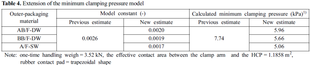
Table 4 shows the constant value of the recalculated model by applying the friction coefficient according to the type of outer-packaging material in contact with the rubber contact pad of the carton-clamp truck arm. The previous 0.0026 value was calculated based on the friction coefficient between the outer-linerboard of the corrugated outer-packaging material and the trapezoidal rubber contact pad, without considering the type of the corrugated outer-packaging material.
The estimated minimum clamping pressure ranged from5.06 to 5.96 kPa, using a one-time handling weight of 3.52 kN and a real contact area of 1.1858 m² between the clamp arm and the HCP, applied to the model in Equation (1) with the onstant value shown in Table 4. As shown in Fig. 8, when the outer-packaging material was BB/F, the slippage of the HCP differed by approximately 12% from the 5 kPa boundary point, showing little change and relative similarity. Therefore,it is believed that the minimum clamping pressure can be reasonably estimated through an FEA-based simulation of carton-clamp truck handling.

Conclusions
Carton-clamp trucks are designed to handle equipment without using pallets, offering strengths in cost and efficiency within factories and storage facilities. As palletless handling by carton-clamp trucks expands across various industries, the need for computer simulations to optimize clamping pressure,the most critical factor in carton-clamp truck handling, is growing. In this study, an ana lysis model, representing a portion of the entire model of the target heavy-weight corrugated package (HCP, L ×W× D = 1,003 × 980 × 1,880 mm, weight= 1,760 N), was defined. The representative load acting on this model was calculated using existing research, and FEA was performed on the slippage of the HCP during cartonclamp truck handling. Based on the FEA simulation, key factors such as the shape of the rubber contact pad were a nalyzed, and the test-based minimum clamping pressure and FEA results were compared. The detailed research findings are summarized as follows:
1) As a result of the FEA, when the outer-packaging material of the HCP was BB/F-DW, the slippage of the HCP between both clamp arms of the carton-clamp truck decreased with increasing clamping pressure, with little change beyond 5 kPa. Among the three types of rubber contact pads, the slippage was s mallest with the trapezoidal pad.
2) Additionally, with the trapezoidal rubber contact pad, the slippage of the HCP was more than 50% s maller in the DW corrugated paperboard compared to the SW corrugated paperboard, and this effect increased with higher pressure. The slippage of the HCP under these conditions is best used for relative comparison rather than as an absolute measure.
3) For the same conditions, the error between the minimum clamping pressure estimated by the improved model and the clamping pressure an alyzed through FEA was approximately 12%. Therefore, if the physical properties applied to FEA are refined, the FEA-based simulation technique developed in this study can accurately estimate the minimum clamping pressure during cartonclamp truck handling.
References
1. Cascade Corporation. Bring palletless handling to your operation.Portland, USA. 2011.
2. Spencer, D.K. and Ebeling, C.W. 2011. Push/Pull & Slipsheet Handling Manual. Global Solutions in Materials Handling,Cascade Corporation.
3. Wisconsin lift truck Corp. http://www.wisconsinlift.com/product-type/carton-clamps/.
4. Stewart, J. and Batt, G. 2005. Clamp truck simulation in the laboratory environment. Proceedings of Dimension, Orlando,Florida, USA.
5. Singh, J. et al. 2015. Carton clamp test methodologies and the effects on load containment and retention. Packaging Technology and Science 28(1): 15-30.
6. Park, J.M., Kim, J.S., Park, J.H., Horvath, L. and Kim, G.S.2017. Numerical ana lysis of clamping pressure during carton clamp handling of heavyweight corrugated packages.
International Journal of Agricultural and Biological Engineering 10(5): 25-34.
7. Park, J.M., Choi, S.I., Park, J.H., and Chung, H.M. 2021.Vibration Measurement and An alysis in Carton Clamp Truck Handling. International Journal of Industrial and Systems
Engineering 37(2): 241-264.
8. ASTM D 6055-2014: Standard test methods for mechanical handling of unitized loads and large shipping cases and crates.
9. ISTA 3B: Packaged-products for less-than-truckload LTL shipment.
10. Park, J.M., Choi, S.I., Kim, J.S., and Jung, H.M. 2019. Labbased Simulation of Carton Clamp Truck Handling - Frictional Characteristics between Corrugated Packages. Korean
Journal of Packaging Science & Technology 25(3): 131-137.
11. Park, J.M., Chang, S.W., and Jung, H.M. Numerical Prediction of Equivalent Mechanical Properties of Corrugated Paperboard by 3D Finite Element An alysis. Appl. Sci. 2020,10, 7973.
12. MiDAS IT. An alysis Manual (2018R2); MIDAS IT: Seoul,Korea, 2018.
13. Khan, A.S., Baig, M., Hamid, S., and Zhang, H. 2010.Thermo-mechanical large deformation responses of Hydrogenated Nitrile Butadiene Rubber (HNBR): Experimental results. International Journal of Solids and Structures 47:2653-2659
AUTHOR

FROM
KOREAN JOURNAL OF PACKAGING SCIENCE & TECHNOLOGY
Vol. 31, No. 2 89~95 (2025)
https://doi.org/10.20909/kopast.2025.31.2.89