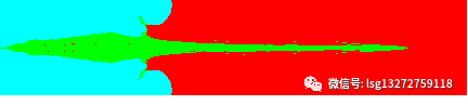
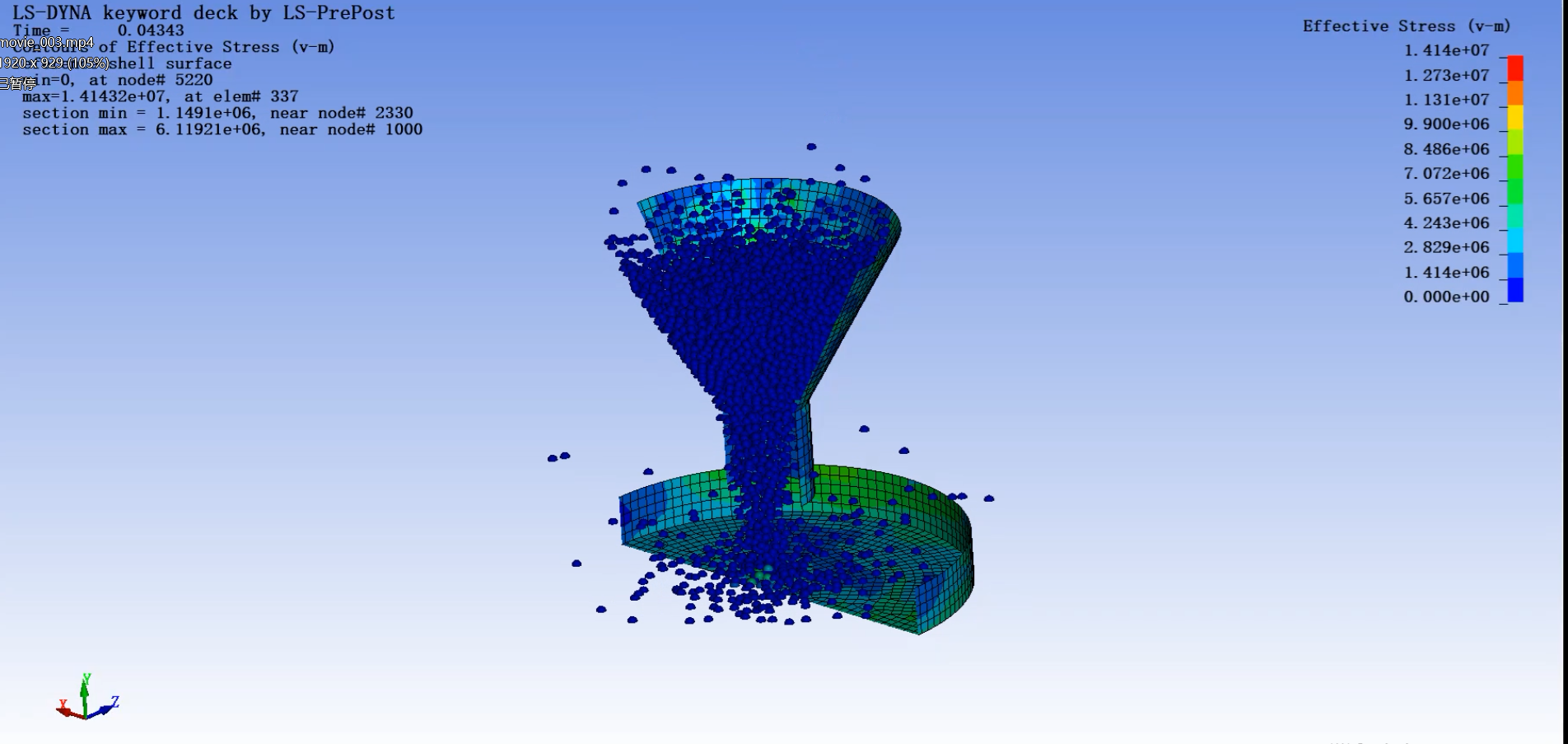
案例(AUTODYN):射流形成、拉伸、映射及侵蚀靶板
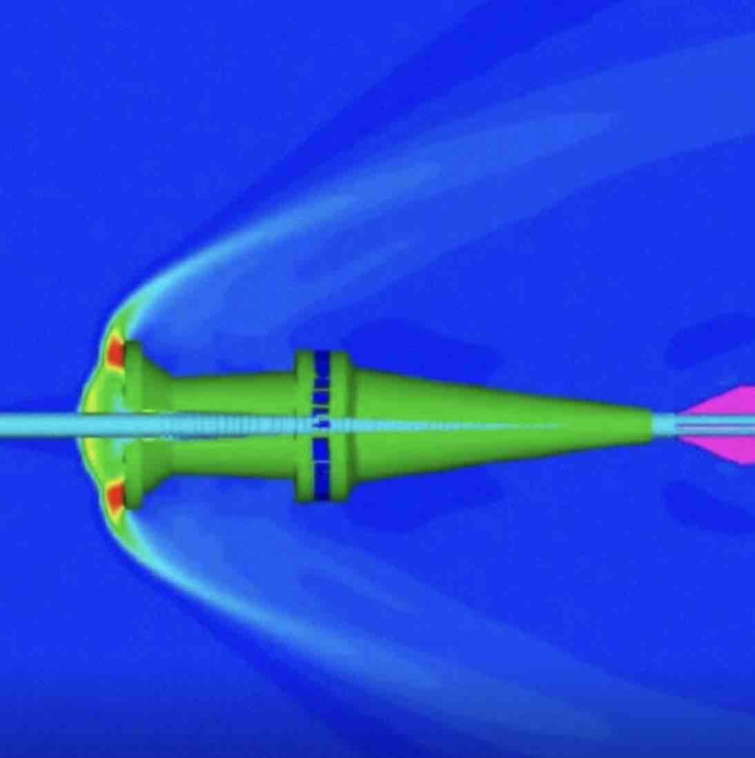
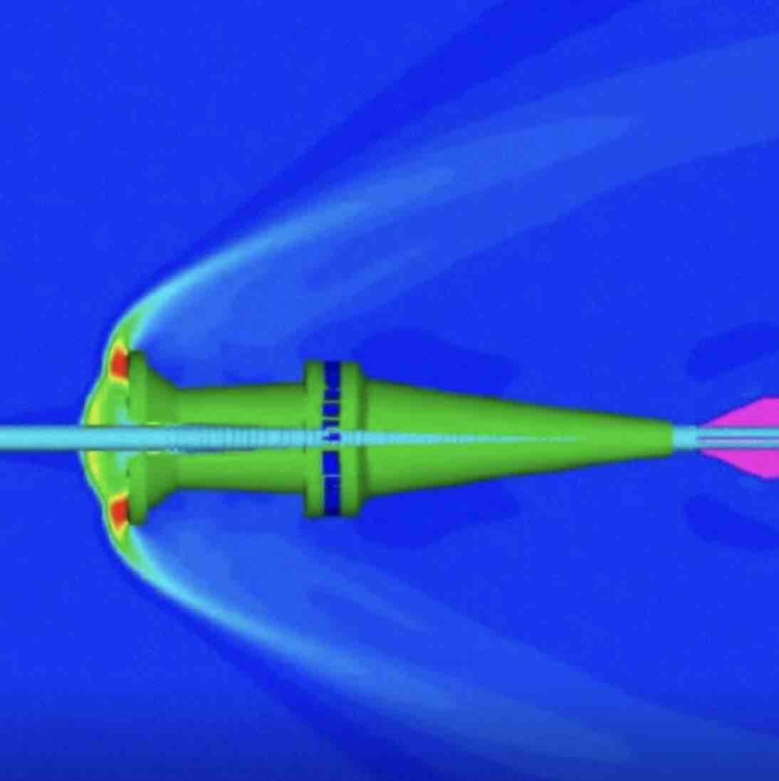
(1)射流形成和拉伸
Part 1 –Axial 2D Shaped Charge Jet Formation
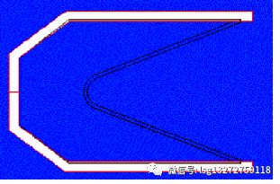
• New Model
– Ident: 2DShaped
– Symmetry: 2D and Axial
• Define Materials
• Load AL2024T351 (Shock –JC), Copper (Shock –none) and TNT.
• Modify AL2024T351
– Add failure to the model (plastic strain of 25%)
– Add erosion to the model: instantaneous geometric strain at 250%.
• Modify TNT
– Under cutoffs, change the minimum density factor to 1.e-6.
• Create a New Material
– Name = air
–EOS is ideal gas: r ref = 1.225e-3, γ = 1.4, Tref = 288, cv = 717.5
• Define Initial Conditions
– Name =StillAir.
– Material = air
– Internal Energy = 206640 J.
• Define Boundary Conditions
– Name = FlowOut,
– Type =Euler flowout.
• Define Part
– Name = Space
– Solver = Euler
– Select Part Wizard
– Select Box: X origin = -100, Y origin = 0.0, DX = 275, and DY = 100
– Define cells in I = 550, Cells in J = 200
– Grade zoning in I, 225*0.25 mm, centred
– Grade zoning in J, 100*0.25 mm, lower J.
– Fill with initial condition: StillAir
• Fill Euler Part
– Rectangle
• x1,x2,y1,y2 = -50, -3, 0, 20
• Fill inside with TNT
– Quad
• Points = (-3,10), (84,43), (-20,43), (-50,20)
• Fill inside with TNT
– Ellipse
• X centre = 0, Y centre = 0.0, X semi-axis = Y semi-axis = 10
• Fill Inside with initial conditionStillAir
• Import from TrueGrid
– Open liner.zon
– Import the part LINER as Lagrange
– Fill part with Copper
• Part Fill LINER into the Euler part
– Select the subgrid LINER and the material TNT to replace.
– Repeat this, but select the material AIR to be replace.
• Delete the part LINER
• Define Boundary Conditions
– I line, I = 1, J = 1, 201, boundary: Flowout
– J line, I = 1, 501, J = 201, boundary: Flowout
•load from part library casing.slb
• Define Lagrange/Lagrange Interactions
– Gap size = 0.2
• Define Euler/Lagrange Interactions
– Select Automatic (polygon free)
• Define Detonation
– Press Line
–Point 1 = (-4.95E+01, 0.00E+00)
–Point 2 = (-4.95E+01, 1.00E+01)
– Initiation time = 0.00E+00
– Range of Influence = Unrestricted
• Define Wrapup Criteria (Controls)
– Cycle Limit = 10000, Time Limit = 0.04, Energy fraction = 0.05
• Define Save Times (Output)
• Start time = 0, End time = 10000, Increment = 0.001
• Save and Execute
Part 2 –Rezoning the Euler Mesh and Continuation of Jetting
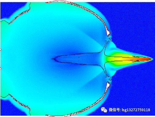
• Open Model of the previous simulation at time 40μs(cycle 2619)
• Delete Part Casing
• Modify Euler part IJK Range
– New I range = 101-651
– New J range = 1-133
• Manual Zoning (Euler Part)
– Define Node
• I = 551, J = 1, X = 342.0 , Y = 0.0
– Define Line
• IJK range: I = 451,551 J = 1,133
• I varies, J index = 1, Geom. ratio = 1.0
– Define Surface
• IJK range: I = 451,551 J = 1,133
• Fill Block
–I = 451, 551 J = 1, 133
– With initial condition StillAir
• Define Wrapup Criteria (Controls)
• Cycle Limit = 10000
• Time Limit = 0.06
• Energy fraction = 0.05
• Save and Execute.
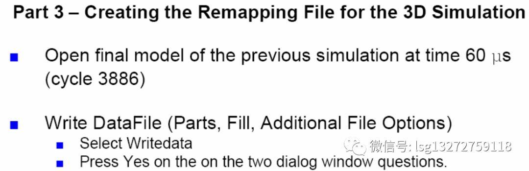
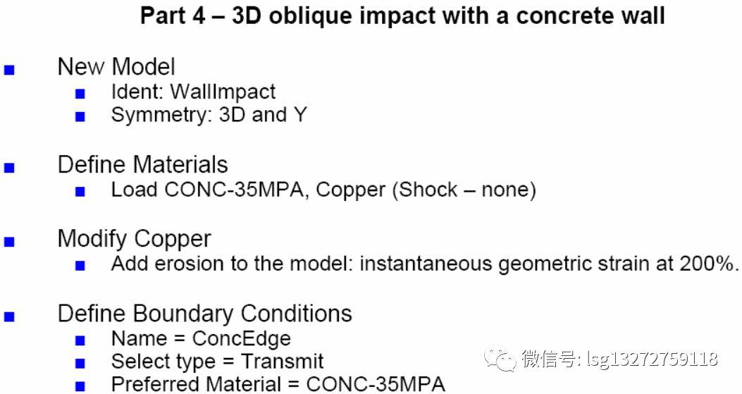
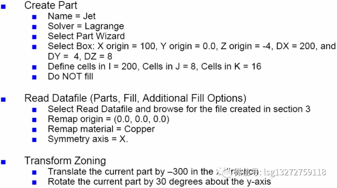
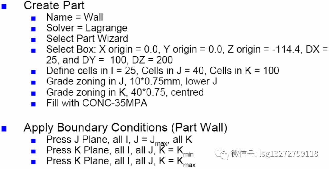
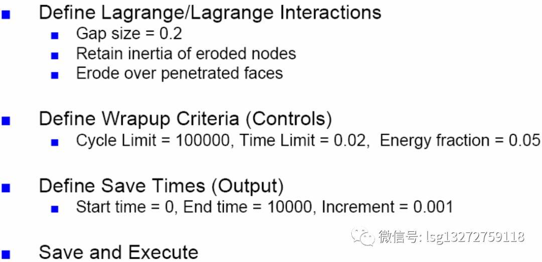
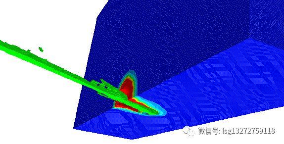
(2)射流映射和侵彻靶板