
Simpack AeroDyn (OpenFAST)气动力介绍
This Force Element integrates the OpenFAST aerodynamic solver with the structural simulation environment to compute aerodynamic loads on wind turbines and transfer them to the structural model.The coupling allows aerodynamic forces generated by the wind field to interact with structural components such as towers, nacelles, hubs, and blades.
Overview
Interface to Aerodyn
Aerodynamic Input Directory
Reference Markers
Node Sets
Wind Field (Input and Visualization)
Turbine Configuration
Aerodynamic Load Transfer
Overview
The Force Element enables the simulation of wind turbine aerodynamics by connectingSimpack with the OpenFAST aerodynamic modules. During the simulation, structural motion is passed to the aerodynamic solver, which calculates aerodynamic loads based on the wind field and turbine configuration. These loads are then mapped back to the structural model and applied to the turbine components.
This bidirectional data exchange allows realistic prediction of turbine response under varying wind conditions and supports coupled aeroelastic simulations.
The aerodynamic calculations are performed using the OpenFAST framework. The coupling interface manages the communication between theSimpack solver and the OpenFAST modules responsible for aerodynamic computations.
Configuration parameters allow you to specify the OpenFAST version, aerodynamic time stepping, and the location of aerodynamic input files. These settings ensure compatibility between the structural model and the aerodynamic solver.
You can use this Force Element instead of Force Element 241: AeroDyn V13 or 237: AeroDyn V15 (OpenFAST).
Differences between Force Element 237 and 241:
· Aerodynamic loads on tower
· Modeling of aerodynamically different rotorblades
· Wind field graphical representation
Differences between Force Element 237 and 247, as well as differences above:
· Multiple rotors and/or turbines
· Improved unsteady aerodynamics and wake modeling
Interface to Aerodyn
Simpack communicates the structural position, orientation and velocities of the tower, hub and blades to AeroDyn. AeroDyn calculates the aerodynamic forces and torques that act on the rotorblades and the aerodynamic forces on the tower of the wind turbine. These forces and torques are communicated back to Simpack. Simpack applies the forces and torques on the aerodynamic Markers or Node sets. For more information, refer to the AeroDyn documentation, https://ebranlard-openfast.readthedocs.io/en/f-ff-doc/source/user/aerodyn/index.html.
InflowWind is used to calculate the undisturbed wind velocities within the defined wind field at the required coordinate positions.
The communication interval between AeroDyn andSimpack uses discrete time steps, which must be set.
Aerodynamic Input Directory
The Aerodynamic input directory contains the following aerodynamic file: The main AeroDyn input file ('aerodyn.inp' ) that will be communicated to AeroDyn.
You can select one Aerodynamic input directory for each wind scenario containing the required AeroDyn input file.
In addition, you need to define the following files:
· Blade aerodynamic definition files dat
(these are called from the 'aerodyn_v15.inp' file)
· Profile polar files dat (these can be located to the aerodynamic input directory or to another folder and are called from the Blade aerodynamic definition files)
An example of an AeroDyn input directory with input files is stored in the example model.
Reference Markers
You will need to set the following Markers:
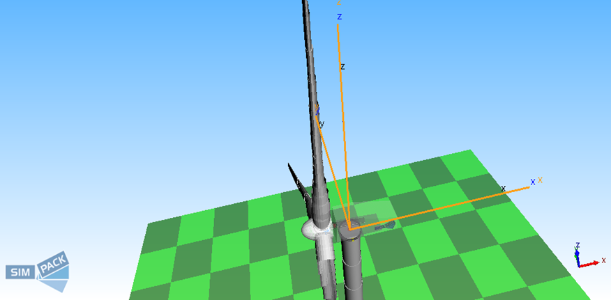
Inertial Reference Marker: This Marker defines the reference system in AeroDyn and it is generally located on Isys or a fixed ground body. Position: Fixed with respect to the undeflected tower centerline, the xy-plane defines the ground or still water level for offshore turbines. Orientation: - Z-axis vertically upwards, opposite to gravity. X-axis downwind (zero-degree wind). Right-handed coordinate system.
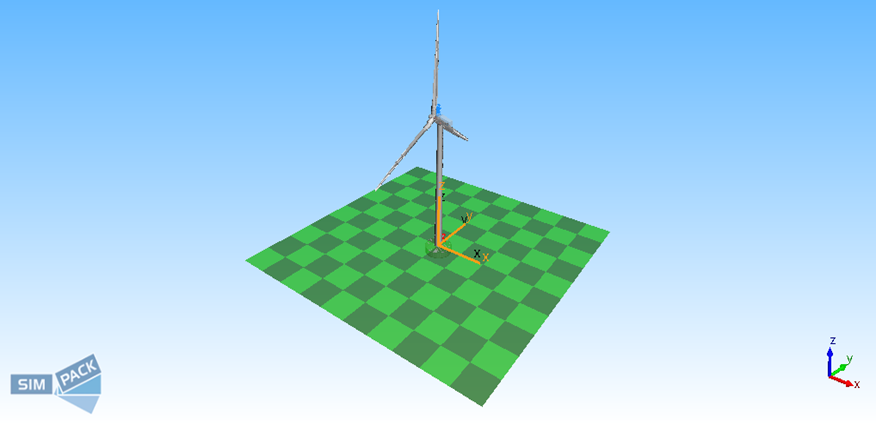
Base Marker: This Marker defines the reference system in AeroDyn for the turbine and it is generally located on Isys of the turbine or a fixed ground body. Position: Fixed with respect to the undeflected tower centerline, the xy-plane defines the ground or still water level for offshore turbines. Orientation: - Z-axis vertically upwards, opposite to gravity. X-axis downwind (zero-degree wind). Right-handed coordinate system.
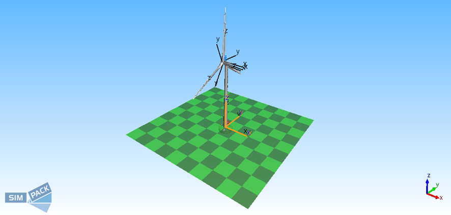
Nacelle Marker: This Marker defines the reference system in AeroDyn for the nacelle, and it is generally located on the nacelle substructure/body. Position is the yaw bearing in nacelle coordinates. Orientation: Z-axis vertically upwards, opposite to gravity. X-axis downward (zero-degree wind). Right handed coordinate system.
Hub Markers: The Marker is generally located on the hub body, rotates with the rotor, and teeters in two-bladed models. Position: Intersection of the rotor axis and the plane of rotation (non-coned rotors) or the apex of the cone of rotation (coned rotors). Orientation: x-axis: pointing along the hub centerline in the nominal downwind direction, z-axis: perpendicular to the hub centerline with the same azimuth as blade 1. Right-handed coordinate system.
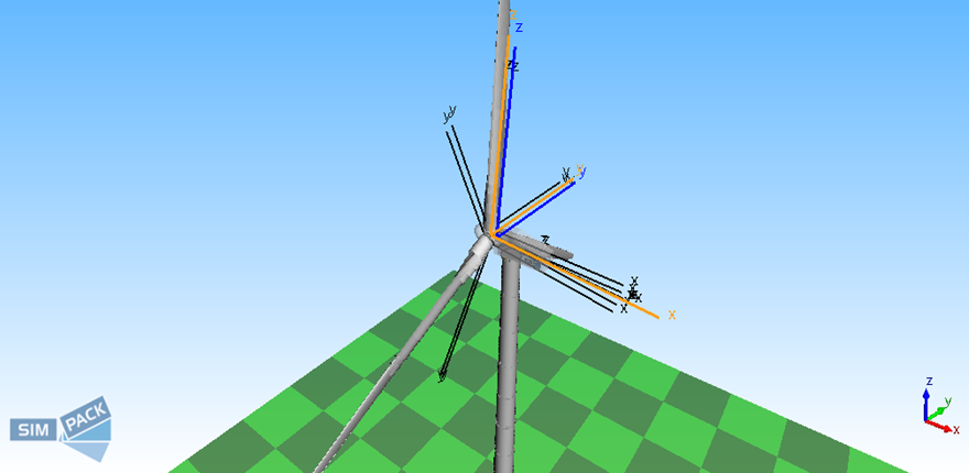
Blade Root Markers: These Markers are generally located on the blade bodies and pitch with the blades. Position: Intersection of the blade's pitch axis and the blade root. Orientation: y-axis: pointing toward the trailer edge of blade i and parallel with the chord line at the zero-twist blade station, z-axis: Pointing along the pitch axis toward the tip of blade (i = 1, 2, or 3 for blades 1, 2, or 3, respectively). Right-handed coordinate system.
Node Sets
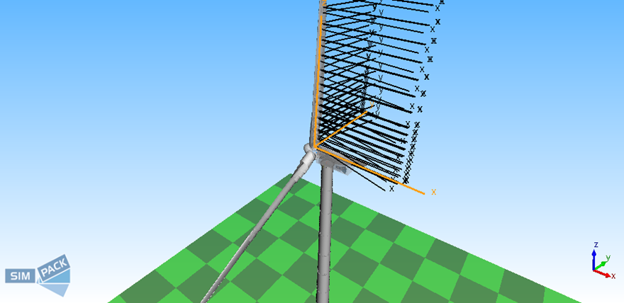
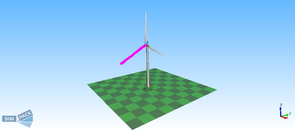
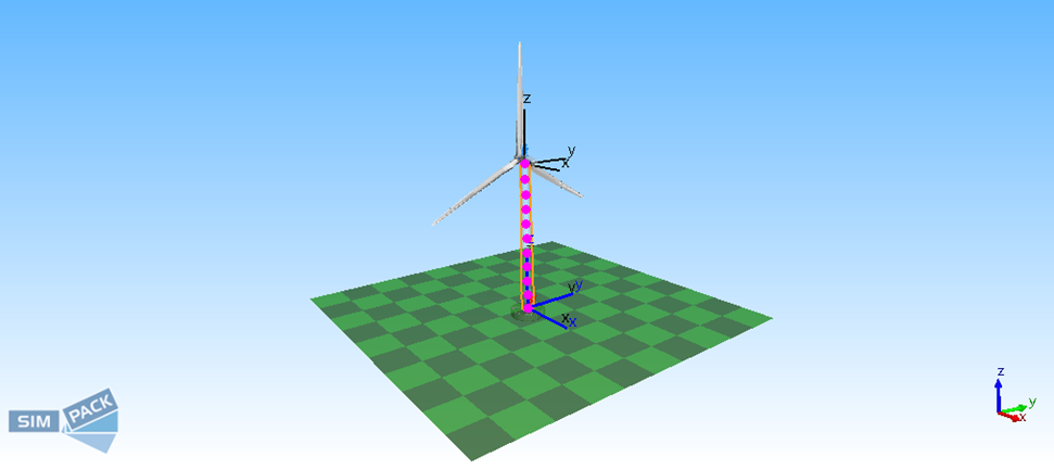
You will need to set the following Node Sets: Aerodynamic Node Sets on the Blades/Tower: The aerodynamic Node sets on the Blades and Tower are required for sending positions, velocities, and orientations to AeroDyn where the resultant aerodynamic forces are calculated. AeroDyn needs to know the zero position (Body Zero Marker Location - BZML) of all coupling aerodynamic Markers on the turbine. The zero position of the turbine is defined as the turbine's state with zero applied aerodynamic forces, zero gravity, zero deformation, first rotorblade vertically upwards, pitch angle=0, etc.
For more information, see the OpenFAST documentation inhttps://ebranlard-openfast.readthedocs.io/en/f-ff-doc/.
Wind Field (Input and Visualization)
The aerodynamic loads acting on the turbine depend on the wind conditions defined in the simulation. Wind data is provided through the wind field configuration, typically using the InflowWind module of OpenFAST.
The wind field describes the spatial and temporal distribution of wind velocity across the rotor area. The aerodynamic solver uses this information to calculate forces acting on the turbine blades and other exposed components.
The Inflow Wind input directory contains:
· The main Inflow Wind input file (called 'inflowwind.dat') that will be communicated to InflowWind.
· The wind field files.
An example of an InflowWind input directory with input files is stored in the example model.
InflowWind can deliver the undisturbed wind speed vectors at any point within the defined wind field. This data can be used for the visualization of the wind fields. TheForce Element allows you to enable the following:
· 3D Wind visualization via surface mesh. 2D surface mesh in the yz-plane representing the x-components of the wind field velocities at each grid point can be visualized. The wind field mesh is a time invariant grid in the yz-plane of the inertial reference Marker for wind propagation direction=0. The wind field mesh is equidistantly distributed and aligned to the hub center. The grid follows the rotation of the wind that is set in InflowWind; it is rotated about the z-axis of the inertial reference Marker. You can define the scaling, contouring, and displacement of the mesh. The undeformed mesh can also be visualized in the animation.
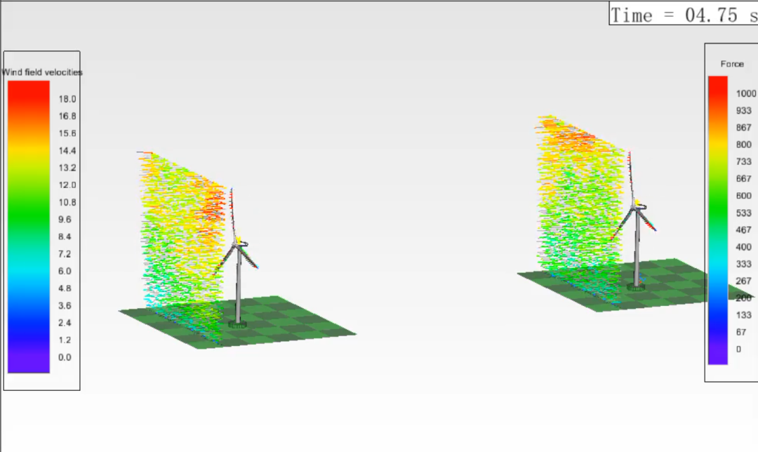
· 3D Wind visualization via vectors. Vector arrows representing the wind field velocities at each grid point can be visualized. The vector arrows can be animated at each grid point via drag. You can scale the length and width of the vectors independent of other force arrows in the Animation. You can visualize also the undeformed grid in the Animation and give an offset of the entire grid and vectors in the x-, y-, and z-direction.
For more information, seeMesh and Field Results.
Turbine Configuration
Each turbine included in the simulation must be defined with its geometric references and structural connections. These definitions provide the aerodynamic solver with information about the physical layout of the turbine.
The configuration typically includes the base reference, nacelle position, hub location, rotor blades, and tower structure. This information ensures that aerodynamic loads are applied at the correct locations in the structural model.
A specific blade order is required. For an observer in front of the turbine looking downwind in the positive x-direction, the blade number increases in the clockwise direction. During operation at a fixed point on the tower, for example, the blades will then pass in the following order 3-2-1.
Application of Forces on the Rotorblades and Tower: You can apply the aerodynamic forces to the rotorblades and the tower by selecting one or multiple flexible Body node sets over which the aerodynamic forces are automatically applied and linearly distributed over the tower/blades.
Aerodynamic Load Transfer
Aerodynamic forces calculated by the solver are transferred to the structural model using node-based load mapping. Structural node sets associated with turbine components receive the aerodynamic loads generated during the simulation.
This load transfer mechanism ensures that aerodynamic forces influence the structural response of the turbine, enabling accurate aeroelastic simulations of rotor blades, towers, and supporting structures.
Aerodynamic Output Data
The aerodynamic solver can generate output data describing the aerodynamic behavior of the turbine. These outputs include aerodynamic forces, rotor performance metrics, and blade-level aerodynamic quantities.
The output data can be used for performance evaluation, structural an alysis, and validation of aerodynamic models.
You can select how you want to visualize the aerodynamic forces and torques on the blades and tower inSimpack Post.
The follow three options are available for the blades:
· Normal and tangent to the rotor-plane, and torque. The orientation is not dependent on the pitch angle.
· Lift, drag, and torque. The orientation is dependent on the pitch and twist angle, wind direction, and rotor speed.
· Flat, edge, and torque. The orientation changes with the changing pitch angle.
The follow two options are available for the tower:
· Normal and tangent forces. Orientation corresponding to the Inertial reference Marker.
· Drag Forces. Direction dependent upon the changing wind direction.

.png?imageView2/0/w/480/h/270)

