HyperMesh 高级培训教程,聚焦高级几何清理、网格划分技术和宏命令开发-英文版122页

摘要:
本文为 HyperMesh 高级培训教程,聚焦高级几何清理、网格划分与宏命令开发。先讲解单元质量评价标准,通过实操案例介绍特征抑制、定点修正、复杂特征网格处理等几何清理方法,搭配去 feature 工具优化模型拓扑,提升网格质量。随后系统讲解 HyperMesh 宏菜单结构、宏命令语法与自定义按钮制作,实现模型保存、截图、质量检查等流程自动化。还结合 Tcl/Tk 脚本扩展交互功能,支持参数输入、文件选择与二次开发,附完整命令清单与案例,帮助用户高效完成复杂模型前处理与工作流定制。
HyperMesh Advanced Training
For technical support, contact us at:
Copyright © 2001 Altair Engineering, Inc., All rights reserved.
Altair® HyperMesh® Advanced Training
Trademark Acknowledgments:
Altair HyperMesh is a registered trademark of Altair Engineering, Inc.
All other trademarks and registered trademarks are the property of their respective owners.
Comments concerning the training material may be made to documentation@altair.com.
Table of Contents
Preface...................................................................................................................1
Section 1: Advanced Geometry Clean-up and Meshing Techniques............3
Element Quality Criteria...................................................................................................3
Exercise 1: Suppressing features adversely affecting element quality................5
Exercise 2: Adjusting fixed points to correct surface edge definitions..................9
Exercise 3: Meshing around a troublesome feature...........................................14
Working with Defeaturing and Geometry Cleanup Tools...........................................23
Exercise 4: Preparing the bracket.......................................................................25
Exercise 5: Preparing the base component........................................................32
Exercise 6: Meshing the parts............................................................................36
Section 2: HyperMesh Macros.......................................................................41
Overview..........................................................................................................................41
What is a HyperMesh Macro..........................................................................................42
The Macro Menu..............................................................................................................42
Page.....................................................................................................................43
Display.................................................................................................................43
Shortcuts..............................................................................................................44
Tool......................................................................................................................44
Files Associated with HyperMesh Macros...................................................................46
HyperMesh options Panel..............................................................................................47
HyperMesh Macro Commands......................................................................................47
Exercise 1: Creating a button.............................................................................49
Process for Creating Basic HyperMesh Macros..........................................................52
Exercise 2: A macro to save the model..............................................................53
Exercise 3: A macro to create a reverse video JPEG........................................57
Creating HyperMesh Macros Using Tcl........................................................................61
Syntax of Macros vs Tcl/Tk..................................................................................62
Creating Macros using Tcl/Tk..............................................................................62
Tcl/Tk Help.......................................................................................................................63
Exercise 4: Create a macro to invoke a Tcl script..............................................64
Exercise 5: Create a macro to save a file to a user-specified directory and
filename...............................................................................................................65
Exercise 6: A macro that checks the model for elements having a Jacobian
below a user specified value................................................................................68
Appendix A: HyperMesh Macro Menu Commands......................................73
Macro File Example.............................................................................................73
Command List.................................................................................................................75
*appendmark().....................................................................................................75
*beginmacro()......................................................................................................76
*callmacro()..........................................................................................................77
*createbutton().....................................................................................................78
*createbuttongroup()............................................................................................80
*createlistpanel()..................................................................................................82
*createmarklast()..................................................................................................83
*createmarkpanel()..............................................................................................84
*createtext().........................................................................................................85
*endmacro().........................................................................................................86
*enterpanel()........................................................................................................87
*includemacrofile()...............................................................................................89
*nextmacrofile()....................................................................................................90
*prevmacrofile()....................................................................................................91
*pushmacrofile()...................................................................................................92
*setactivegroup()..................................................................................................93
*setactivepage()...................................................................................................94
*setbuttongroupactivecolor()................................................................................95
Appendix B: HyperMesh Tcl/Tk Interface......................................................97
Overview..........................................................................................................................97
Executing Tcl/Tk Scripts................................................................................................97
GUI Development............................................................................................................98
Additional HyperMesh Commands....................................................................100
hm_answernext..................................................................................................100
hm_complist.......................................................................................................101
hm_elemlist........................................................................................................102
hm_errormessage..............................................................................................103
hm_getentityvalue..............................................................................................104
hm_getfilename.................................................................................................105
hm_getfloat........................................................................................................106
hm_getint...........................................................................................................107
hm_getmark.......................................................................................................108
hm_getstring......................................................................................................109
hm_markclear....................................................................................................110
hm_nodelist........................................................................................................111
hm_nodevalue...................................................................................................112
hm_redraw.........................................................................................................113
hm_usermessage..............................................................................................114
Example.............................................................................................................115
Preface
Who should attend
This course is designed for students who have attended HyperMesh Basic Training and have a working knowledge of HyperMesh. It covers two topics. The first is advanced geometry clean-up and meshing techniques. The second is macros and macro creation, a tool to improve your productivity using HyperMesh.
Even if you have no experience writing any program code, by the end of this session, you will be successful at creating your own macros. Each section also includes “hands-on” exercises to help you become comfortable with the new techniques presented here.
Manual notations
This manual uses the following notations.
• courier for text that you type in
• bold italic for panel names, button names, and sub-panel names.
Information that is of importance or warning messages will appear in a note box.

Macro commands may occasionally be longer than the text line of this document.
In those cases, the text wraps to the next line and is slightly indented. When asked to enter such a command, type the entire command ignoring the wraparound. This will ensure the system can accurately interpret the command you entered.
For more help
Should you desire additional help with material in this course, see the back of the title page of this manual for contact information.
Comments about this manual may be directed to documentation@altair.com.
Section 1: Advanced Geometry Clean-up and Meshing Techniques
Geometry cleanup and automeshing, often cited as the most time consuming aspects of Finite Element An alysis (FEA) modeling, are the most critical aspects in generating a quality mesh that will give accurate an alysis results. A methodical approach to geometry cleanup and automeshing activities can save a great deal of time in the an alysis process and assist in obtaining dependable results.
Element Quality Criteria
In FEA modeling, element quality greatly effects the accuracy of the an lysis results. Many modern FEA solvers have routines to compensate for some measure of poor element quality, but it is not a good practice to rely on these compensations. The FEA modeler must take into consideration element quality,
and thereby judge whether the an alysis results are meaningful.
The ideal four-node (quad) plate element is a planar square. Two types of errors can result from translating a single node. If one of the nodes is translated in the plane of the remaining nodes, the interior angles change and the edge lengths vary between sides introducing skew and aspect ratio into the element. If one of the nodes is translated out of plane of the others, the result is warpage.
With first order tria elements warpage is not possible, but aspect ratio and skew remain valid measures of element quality. The element checks in HyperMesh test these properties and provide feedback as to the quality of the element.
Keep element quality criteria in mind while observing the geometry of the model. When trying to determine whether or not to cleanup the geometric feature, ask yourself the following questions.
Is this feature important to my an alysis? Often designers model details that are unimportant in FEA. Tapers, fillets, steps and ridges in sheet metal parts, while required for manufacturing, can often be ignored in an alysis.
How will this feature affect my mesh and element quality? Consider the benefits and consequences of removing the feature versus meshing it. With HyperMesh, often the simplest way to answer this is to mesh with the feature, then mesh without the feature, and compare the results.
Will it be easier to correct the geometry before meshing, or to correct the elements after meshing? As the geometric features become more detailed and complex, it is often easier and faster to mesh around them and correct the mesh afterwards. With the new element cleanup functionality in HyperMesh, correcting element quality becomes a simple, interactive task.
Do I need to mesh the surfaces, or can this part be modeled using other techniques? Sometimes the more basic “surfaceless” meshing tools result in a better quality mesh faster and easier than using the surfaces presented. Tools such as spline, ruled mesh, line drag, spin, skin, and element offset can often be used to accurately represent a part without being confined to the given geometry.
The next five example problems demonstrate how to manage these situations.
Exercise 1: Suppressing features adversely affecting element quality
Step 1: Retrieve the model taper.hm40
In this exercise, use the automesher to create a surface mesh both before and after suppressing unnecessary feature lines. Use the cleanup sub-panel within the automesh panel to avoid extra panel navigation.
Go to the files panel from any page.
Select the hm file sub-panel by clicking the corresponding radio button.
Click in the text field next to file = and select taper.hm40 using the file browser, or type in the file name.
Click retrieve to read the file into HyperMesh.
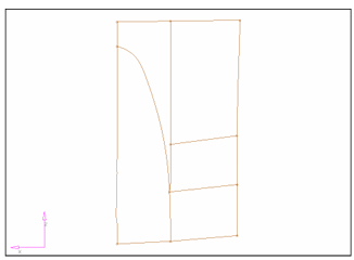
This file contains five surfaces. The surface with a curved edge forms a tail that tapers into a narrow point. This feature, as well as the other trim lines forming the boundaries between the individual surfaces, will result in a less than ideal mesh on these surfaces.
Step 2: Create a baseline mesh
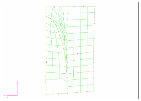
From the 2D page, select the automesh panel.
Select the create mesh sub-panel by clicking the corresponding radio button.
Click on the green surfs button and select all from the pop-up menu.
Click in the text field next to elem size = and enter 25.0
Click mesh to enter the secondary automesh menu.
Click mesh to display the preliminary mesh.
Notice how the curved line results in severely distorted elements. Since the curved line is unimportant to our ana lysis, we can suppress it and improve the element quality.
Step 3: Creating an improved mesh
Click abort to discard the existing mesh.
While still in the main automesh panel, select the cleanup sub-panel by clicking the corresponding radio button.
Click the green line button under toggle: to make that the active entity selector.
Click each of the interior green surface edges to suppress those features.
Return to the create mesh sub-panel.
Click mesh to enter the secondary automesh menu.
Click mesh to display the preliminary mesh.
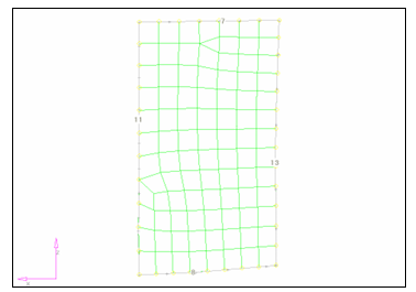
Note the improved mesh quality. Since the baseline meshing operation retains the original mesh densities, the remaining problem areas result from transitions due to the different mesh densities on corresponding sides of the rectangular surface. To fix this, manually adjust these densities or re-calculate the edge
densities.
Step 4: Adjusting element densities
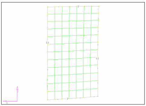
1. Click the green recalc all button to re-compute the edge densities based on the desired 25 mm element size.
2. Click mesh to re-generate the mesh.
3. Click return to accept the mesh and go back to the main automesh panel.
Note the improved consistency in the resulting mesh.
Summary
In this exercise, we used the automesher to point out the problems caused by unnecessary feature lines. By suppressing the lines, the resulting mesh on this surface greatly improved.
详细内容请见附件
免责声明:
本页面/内容部分素材来源于互联网公 开 信 息,旨在传递更多信息,不代表本平台立场。
版权归原作者或机构所有,如涉及侵权,请通过平台联系我们,我们将在核实后第一时间处理。
本平台对转载内容的真实性、准确性不作任何保证,用户需自行判断并承担使用风险。