HyperWorks 10.0 Abaqus 建模与后处理指南-英文版-156页

摘要:
本文为 HyperWorks 10.0 版本下 HyperMesh 与 Abaqus 6.8 的建模及后处理官方指南,先介绍 Abaqus 接口基础配置,包括输入输出模板、用户配置、工具菜单等核心功能。接着讲解模型数据定义,涵盖组件、材料、截面属性设置,支持 Nastran 模型转换与一维单元三维可视化。借助步管理器完成模型与历史数据定义,实现载荷、边界条件与输出请求配置,还可完成螺栓预紧、解析刚性面、接触、单节点单元等高级建模。此外介绍局部坐标系、方向系统定义,Abaqus/Explicit 通用接触与幅值曲线设置,最后说明 HyperView 对静态与复频结果的后处理方法,含云图、矢量图、数据曲线绘制,配套实操案例,完整覆盖前处理到后处理流程。
HyperWorks for Abaqus
Altair Engineering Contact Information
Web site www.altair.com
FTP site
Address: ftp.altair.com or ftp2.altair.com or http://ftp.altair.com/ftp
Login: ftp
Password: <your e-mail address>
©2009 Altair Engineering, Inc. All rights reserved. No part of this publication may be reproduced, trans mitted, transcribed, stored in a retrieval system, or translated to another language without the written permission of Altair Engineering, Inc. To obtain this permission, write to the attention Altair Engineering legal department at: 1820 E. Big Beaver, Troy, Michigan, USA, or call +1-248-614-2400.
Trademark and Registered Trademark Acknowledgments
Listed below are Altair® HyperWorks® applications. Copyright© Altair Engineering Inc., All Rights Reserved for:
HyperMesh® 1990-2009; HyperView® 1999-2009; OptiStruct® 1996-2009; RADIOSS® 1986-2009; HyperCrash™ 2001-2009; HyperStudy® 1999-2009; HyperGraph® 1995-2009; MotionView®1993-2009; MotionSolve® 20022009; TextView™ 1996-2009; MediaView™ 1999-2009; HyperForm® 1998-2009; HyperXtrude®1999-2009; HyperView Player® 2001-2009; Process Manager™ 2003-2009; Data Manager™ 2005-2009; Assembler™ 2005-2009; FEModel™ 2004-2009; BatchMesher™ 2003-2009; Templex™ 1990-2009; Manufacturing Solutions™ 2005-2009; HyperDieDynamics™ 2007-2009; HyperMath™ 2007-2009; ScriptView™ 2007-2009.
In addition to HyperWorks® trademarks noted above, GridWorks™, PBS™ Gridworks®, PBS™ Professional®, PBS™ and Portable Batch System® are trademarks of ALTAIR ENGINEERING INC., as is patent # 6,859,792. All are protected under U.S. and international laws and treaties. All other marks are the property of their respective owners.
Table of Contents HyperWorks for Abaqus
Preface.....................................................................................................................1
1. Foundation for Abaqus Modeling......................................................................3
2. Introduction to Defining Abaqus Model Data...................................................7
Section 1: Defining Model Data.........................................................................................8
Section 2: Element Property Assignment, Importing and Include Files...........................20
Section 3: Converting a Nastran Model to Abaqus.........................................................27
Section 4: 3D Visualization of 1D Element with Abaqus models………………………….30
3. Defining Model and History Data With the Step Manager.............................43
Section 1: Define Model Data with Step Manager..........................................................44
Section 2: Define History Data with Step Manager.........................................................50
4. Bolt Pretensioning, Ana lytical Rigid Surfaces, One Node Elements...........63
Section 1: Bolt Pretension...............................................................................................64
Section 2: An alytical Rigid Surfaces...............................................................................68
Section 3: One Node Elements and Contact Definition..................................................81
5. Systems in Abaqus...........................................................................................91
Section 1: *SYSTEM, *TRANSFORM.............................................................................92
Section 2: *ORIENTATION...........................................................................................101
6. Model Setup in Abaqus/Explicit.....................................................................107
Section 1: General Contacts, Boundary Conditions in Abaqus/Explicit.........................108
7. Post Processing Abaqus Results in HyperView..........................................119
Section 1: Post Processing Static An alysis Results......................................................119
Section 2: Post Processing Complex Results...............................................................134
Appendix .............................................................................................................145
Preface
This course manual is based on HyperMesh 10.0, HyperView 10.0, and Abaqus 6.8. HyperMesh is a high-performance finite element pre-processor for major finite element
solvers, such as Abaqus. HyperView is a complete post-processing and visualization environment for finite element an alysis, multi-body system simulation, video, and engineering data.
In a traditional classroom setting, this course manual will help you become proficient with various panels and utilities in HyperMesh that are used to set up models for an alysis with Abaqus. It will also help you to learn about post-processing and viewing Abaqus results in HyperView.
It is suggested that students be familiar with HyperMesh and HyperView before attending this course.
• For students not familiar with HyperMesh and HyperView, the suggested prerequisite HyperMesh and HyperView course is HyperMesh Introduction (Preprocessing for Finite Element An alysis).
• For students familiar with HyperMesh, but not with HyperView, the suggested prerequisite HyperView course is HyperView Introduction (Results Visualization and Data An alysis for Finite Element A nalysis).
Chapter 1 Foundation for Abaqus Modeling
In this chapter, the following topics using HyperMesh will be discussed:
• Abaqus FE input translator
• Abaqus FE output template
• Abaqus Utility Menu
• Abaqus User Profile
• On-line help for HyperMesh-Abaqus interface
The above items are the foundation for interfacing with Abaqus in HyperMesh.
Abaqus FE Input Translator
The Abaqus FE input translator imports Abaqus input files. It is named Abaqus and it supports input files for Abaqus versions 5.8 and above. Select this input translator and import an Abaqus input file from the Import browsers.
Abaqus FE Output Template
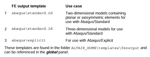
An Abaqus FE output template contains Abaqus specific formatting instructions that HyperMesh uses to create an Abaqus *.inp file. Several templates exist:
Abaqus Utility Menu
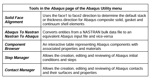
The Abaqus Utility Menu contains five pages of tools, with one page specific to using Abaqus with HyperMesh. The Abaqus page contains tools specific to interfacing with Abaqus. The other four pages are the same pages in the default HyperMesh Utility Menu. Some of the tools in the Abaqus page are described in the table below.
Abaqus User Profile
Users can save time setting up their model by loading the Abaqus User Profile. You can set the User Profile from the Preferences pull-down menu >> User Profiles…
Setting the User Profile to Abaqus also performs the following actions:
• Sets the FE input translator to Abaqus
• Loads the appropriate Abaqus FE output template (standard.2d, standard.3d or explicit)
• Loads the Abaqus Utility Menu
• Makes the graphical user interface Abaqus focused by renaming or removing certain panels and options.
Changing the Abaqus User Profile to another profile, such as OptiStruct, does not alter the
Abaqus model.
On-line Help
HyperMesh on-line help has a reference guide for interfacing with Abaqus. Access help from the Help pull-down menu and by selecting the HyperMesh and BatchMesher item, or by pressing the “h” keyboard key.
In the Contents tab of the left frame of the Internet browser, go to HyperMesh Guide HyperMesh Interfacing with External Products User’s Interfacing with Finite Element Solvers Abaqus Solver Interface.
Chapter 2 Introduction to Defining Abaqus Model Data
In this chapter, the following topics using HyperMesh will be discussed:
• Creating and editing Abaqus components, materials and section properties.
• Viewing images of keywords and data lines in HyperMesh as they appear in the Abaqus input file.
• Reviewing material and property assignments using model browser views.
• Selecting Abaqus entity types for HyperMesh element configurations and creating 1D elements.
• Reviewing a model in the solver browser and exporting an Abaqus formatted input file.
• Assigning properties directly to elements.
• Working with include files.
• Using the Nastran To Abaqus utility to convert models.
• 3D Beam Visualization with Abaqus Models.
Section 1: Defining model data (elements, properties, materials)
HyperMesh Card Images
HyperMesh card images allow you to view images of keywords and data lines for defined Abaqus entities as interpreted by the loaded template. The keywords and data lines will appear in the Abaqus input file as you see them in the card images. Additionally, for some card images, you can define and edit various parameters and data items for the corresponding Abaqus keyword.
Use the Card Editor panel in the tool bar to review and edit card images. Also, for many entities, review and edit their card image from the panel in which they are created, or by accessing the Card Edit option in the context-sensitive menu of the model browser.
*ELEMENT with Section Property
Starting in HyperMesh 9.0 and continuing in HyperMesh 10.0, sectional properties, such as
SHELL SECTION, are defined by the card image of a property collector. In previous versions
sectional properties were defined within a component collector. Elements still belong to a
component collector, but their property assignment is now made by assigning a property to the
component.
The Abaqus keyword
*ELEMENT, TYPE = <type>, ELSET = <name>
is defined by Abaqus elements collected in a HyperMesh component collector. One
*ELEMENT keyword is written to the Abaqus input file for each element type in the component.
The name of the ELSET is the name of the component.
The Abaqus sectional property associated to the *ELEMENT is defined by a property collector’s card image. The property collector itself is associated to the component collector which contains the elements that should assume the associated property. The material that is associated to the property is defined by a HyperMesh material collector which is linked to the property. The diagram below shows how an *ELEMENT and its associated property and material are organized in HyperMesh.
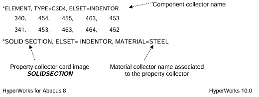
There are many property card images for the Abaqus templates such as SOLIDSECTION, SHELLSECTION, GASKETSECTION, BEAMSECTION, SPRING, JOINT and MASS.
Define an *ELEMENT keyword with an associated sectional property as follows:
1. Create a property collector with a card image and a material collector either from the property collector panel in the toolbar or from the context-sensitive menu in the model browser.
2. If necessary, edit the property’s card image to define data lines and parameters for the sectional property.
3. Reference the property collector to the component collector.
4. Organize elements into the component.
Abaqus Materials
An Abaqus *MATERIAL is a HyperMesh material collector with a card image.
There are four material card images for the HyperMesh Abaqus templates: ABAQUS_MATERIAL, GASKET_MATERIAL (for the Standard templates), CONNECTOR_BEHAVIOR and GENERIC_MATERIAL.
详细内容请见附件
免责声明:
本页面/内容部分素材来源于互联网公 开 信 息,旨在传递更多信息,不代表本平台立场。
版权归原作者或机构所有,如涉及侵权,请通过平台联系我们,我们将在核实后第一时间处理。
本平台对转载内容的真实性、准确性不作任何保证,用户需自行判断并承担使用风险。