首页/文章/ 详情

hypermesh详细划网格资料-电子书

6月前浏览274

第一章 自动划分网格

automesh面板用于对现有曲面进行网格划分。它有两种划分模式:交互(interactive)和 自动(Automatic)。模型的显示与在Geom Cleanup面板中相同,即根据其边的连接状态 来显示。该面板中还包括cleanup,add或者remove points和proj to edge这四个子面板, 它们可以执行很多Geom cleanup面板的功能。 

如果选择交互模式,当选定曲面后,HyperMesh会调用Automeshing模块。automeshing模块包括以下内容:
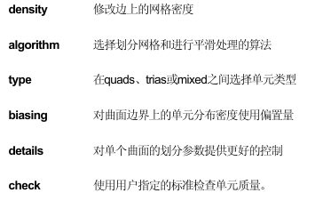
image.png

使用这些面板,用户可以在很大程度上控制划分网格的过程和生成单元的质量。

在automesh 面板上有一个子面板mesh params,用户可以用它来设定单元的尺寸和偏 置量,或者使用弦差算法来划分单元。在使用设定的单元参数之前,需要在creat mesh  子面板上将 element size=切换到 use mesh params。如果没有做到这一点,那么 interactive 或者automatic 子面板执行的划分网格操作会忽略在mesh params 子面板 中的设定。在mesh params 子面板的右半边包含网格划分算法的选项,左半边则包含对 弦差划分方法的设定和相关选项。

如果选择use element size and biasing,HyperMesh会在曲面的边上等距离地按照指定的大致单元尺寸来放置节点。如果选择use chordal deviation,HyperMesh自动根据指定的弦差标准来调整曲面边界上的单元密度和偏置的数值。
55602da1-2a3d-4f90-a0f3-0d2b034d9673.png

练习1.1: 模型准备

在这个练习中,提取一个C 型槽钢的HyperMesh 模型。然后设定一个对这个模型较为适当的单元尺寸。最后检查曲面的连接特性以确定几何中各曲面之间完全“缝合”。


  • 决定并设置单元尺寸

1.在files面板中选择hm files子面板提取c-channel0.hm。

2.在Geom页面上选择length面板。

3.在C型槽钢上竖直横切的筋上,选中一条可以代表网格特征的直线。

4.点击length。

这条直线的长度值出现在length =后面的输入框中,要生成一个四边形网格,沿着这条边分布的单元数量应当大约是12个。用这个单元数量去除这条边的长度就可以计算出单元的尺寸。

5.点击return退出length面板。

6.在永久菜单上选择global面板。

7.点击element size并输入0.25。

现在,当HyperMesh在一个曲面上创建网格时,这个值就成为默认的单元尺寸。可以在 automesh面板中覆盖掉这个值,也可以在互动划分网格模式中修改网格的种子点。

8. 点击return退出global面板。


  • 检查曲面连接特性

1.在宏菜单中,在Display: gfx下点击per进入performance图形模式。

2.在宏菜单中的Display: vis opts下点击3选项将曲面显示为阴影模式并显示自由边、共 享边或非重合边。这个模型所有的内部边要么是共享边,要么是非重合边,与实际相符。 因此该模型可以划分网格了。如果模型内部有自由边,在划分网格时会产生网格连续性方面的问题。 

3.在宏菜单中的Display: vis opts下点击0返回线框显示模式。

image.png

练习1.2: 使用Automesh面板中的Interactive模式

1.在2D页面中选择automesh面板。

2.选择create mesh子面板。

3.点击surfs并选择by collector。

4.选中leftend这个component collector并点击select。

5.点击其复选框激活reset meshing parameters to:选项。

6.将左上角的开关切换为elem size。

image.png


7.将较低的开关设置为quads,要求生成四节点的四边形单元。

8.要将生成的单元自动放到曲面所属的component中,应当将开关切换到elements to surface’s comp。 

9.将最右端的开关切换到interactive,调用互动模式。

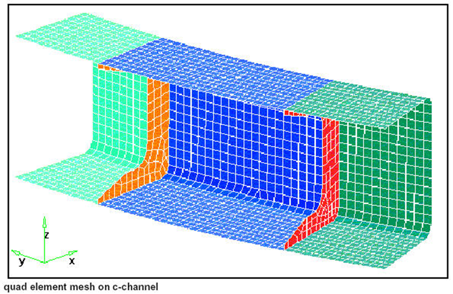
10.点击mesh。

激活automeshing模块。节点的位置被标在曲面的边上。每一条边上都有一个数值与其关联,该数值表示这条边上生成的单元数目。在下一个练习中会看到如何修改这些数值。

练习1.3: 使用Automesh模块的Density子面板

将划分完网格的曲面自动适配到屏幕上

1.点击local view。

2.从弹出菜单中选择fill。

3.将鼠标指针移出弹出菜单退出local view。


  • 使用density子面板

1.选择density子面板。

2.不调整任何设置,点击mesh预览网格。

3.点击adjust edge使其成为当前的边选择器。

4.在图形区中,尝试用左键点击边上的数值来改变边上的单元密度。

单击左键将密度值增加1,单击右键将密度值减小1。一个快速地大幅度改变单元密度的方法就是按住鼠标左键不放,同时将鼠标向上或向下拖动。向上拖动增加单元密度而向下拖动减小单元密度。

5.调整边上的单元密度以后,点击mesh预览发生的变化。

6.点击element size =并输入0.5。

7.点击recalc edge使其成为当前的边选择器。

8.在图形区中,点击一个单元密度数值。

这一步按照0.5的单元尺寸重新计算所选边上的单元密度(四舍五入到最近的整数)。

9.调整边上的单元密度以后,点击mesh预览发生的变化。

10.点击recalc all将所有边上的单元尺寸设置为0.5。

11.点击mesh预览发生的变化。

12.点击element density =并输入10。

13.点击set edge to使其成为当前的边选择器。

14. 图形区中尝试用鼠标左键选择边上的单元密度数值来改变单元密度。这一步将所选边上的单元密度都设为10。

15.在修改完边的单元密度后,点击mesh预览发生的变化。

16.点击set all to将所有的边的单元密度设为10。

17.点击mesh预览发生的变化。


  • 生成最后的网格

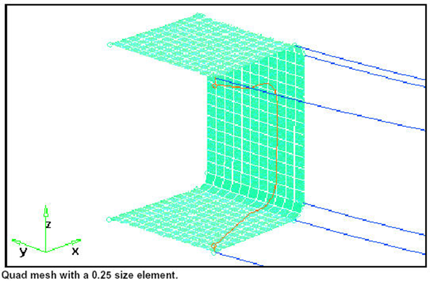
1.点击element size并输入0.25。

2.点击recalc all 将所有边的单元尺寸设为0.25。

3.点击mesh预览发生的变化。

4.点击return接受所划分的网格并返回automesh面板。
52847dcc-bf3e-44aa-8788-69230dcb3a55.png

image.png

练习1.4: 使用Automesh模块的Algorithm和Checks子

  • 面板

在这个练习中使用algorithm子面板改变HyperMesh对曲面进行网格划分的算法。然后使用checks子面板检查单元质量,并观察哪种算法生成的单元质量最好。

HyperMesh中四种不同的划分网格算法是:

        矩形算法; 

        三角形算法;

        五边形算法; 

        自由算法。 

规则的划分算法趋向于产生更好质量的四边形单元。对这些算法来说,曲面必须是有一定形状特征的矩形、三角形或五边形。自由算法则可以在最多种类的曲面上划分网格而不考虑其几何形状。

  • 使用algorithm子面板

1.在disp面板中关闭leftend这个component collector中的单元。

2.在automesh面板中点击surfs并选择by collector。

3.点击rib1这个component collector,并点击select。

4.点击mesh调用automeshing模块。

5.点击local view中的f将被划分网格的区域在屏幕上自适应放置。

6.选择algorithm子面板。

image.png

7.点击mesh预览网格。

bc746408-d265-411d-a3d3-d04ae9d5ac89.png


8.将meshing algorithm:设为map as rectangle。

9.点击set surf。

10.在图形区中,用鼠标左键点击曲面中心的蓝色图标改变曲面上的网格划分算法。

11.点击mesh并注意两种划分方法结果的区别。
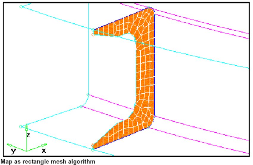
5f0284a5-136d-4cab-b451-5d61cba8c081.png

  • 使用checks子面板

checks子面板用于在接受网格之前执行单元检查。在对应的输入区里输入一个数值就可以改变检查的门槛值。所有不合格单元被用白色的高亮度显示,同时在标题栏中会出现一个信息提示不合格单元的百分比以及最差单元的对应数值是多少。

1.选择checks子面板。

2.点击aspect检查单元的长宽比。

3.检查jacobian,quads: min angle和quads: max angle。

4.选择algorithm子面板。

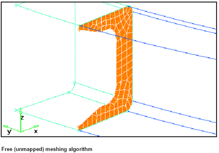
5.将划分算法设为free (unmapped)。

6.点击set all。

7.点击mesh用自由算法重新对曲面进行网格划分。

8.重复上述步骤1~3,注意单元质量的变化。

9.点击return接受生成的单元并返回automesh面板。

image.png

练习1.5: 使用Automesh模块的Type和Biasing子面板

在这个练习中使用type子面板将单元的构造从四边形改为三角形和混合型。然后使用 biasing子面板来修改曲面边界上节点的分布。 


  • 使用type子面板

1.在display面板中关闭rib1这个component collector中的单元显示。

2.在automesh面板中点击surfs并选择by collector。

3.选择rib2,middle和rightend这三个component collector并点击select。

4.点击mesh调用automeshing模块。

5.点击local view中的f将被划分网格的区域在屏幕上自适应放置。

6.点击mesh预览划分的网格。

7.选择type子面板。

与algorithm子面板类似,在每一个曲面上都出现一个蓝色的图标,它标示出这个曲面上存在的网格的类型。因为此时在automesh面板上定义的是四边形,所以所有的曲面都有一个四边形的图标。

8.将element type: 设为trias。

9.点击set surf。

10.在图形区中用鼠标左键点击曲面上的蓝色图标,并选择一个不同的单元类型,就能改变曲面网格的单元类型。

11.点击mesh预览这些变化。
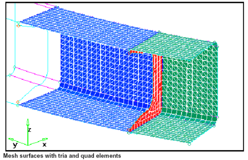
8cc09de2-729f-4244-b189-b5fb91f72115.png


  • 使用biasing子面板

1.选择biasing子面板。

2.将bias style:设置为bellcurve,然后点击set all。

每条边上都会有一个表示偏置类型的图标。使用adjust edge或者set edge选择器来修改每条边上的偏置值。

image.png

3.点击bias intensity =并输入3.0。

4.点击set edge并选择rightend中的支撑筋板的两条边。

5.点击mesh预览发生的变化。
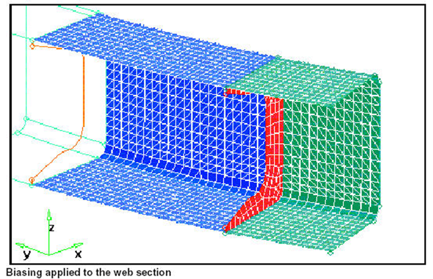
be6f588d-e1d6-48ef-b49e-90de97693d96.png

6.点击return接受划分的网格并返回automesh面板。

7.点击return退出automesh面板。

image.png

练习1.6: 合并节点

在这个练习中,要保证单元之间的连续性,必须合并模型的所有重节点。这一合并操作会识别出任何有重节点的位置,重节点是指两个或更多的节点,其间距小于指定容差。在合并过程中,重节点中的一个节点被保留,而其它节点则用这个被保留的节点的定义来替代。

1.在宏菜单上的Display: elems下点击on。然后将模型在屏幕上重新fit。

2.在Tool页面上选择edges面板。

3.将开关设置为comps并选择所有component collector。

4.将tolerance设为0.010,然后点击preview equiv。

即使所有的几何都完整地“缝合”在一起,在不同的步骤中自动划分网格也不能保证生成的单元在曲面边界上有共同节点。但是,如果在同一个自动划分网格的步骤中同时对多个连续曲面进行网格划分,例如同时对rib2、middle和rightend三个component的曲面同时划分网格,曲面边界上所有的节点都是相同的,这就保证了单元的连续性。

5.点击equivalence将模型缝合到一起。

6.点击return退出edges面板。

image.png

练习1.7: 使用弦差(Chordal Deviation)来划分网格

弦差(Chordal deviation)经常被用于金属成型分析,这种分析要求在大曲率的区域集中大量的单元。如果需要更多的关于利用弦差划分网格技术的信息,请参考在线帮助。


  • 删除单元

1.在键盘上按下F2调用delete面板。

2.将开关设置为elems。

3.点击elems并选择all。

4.然后点击delete entity。

5.点击return退出delete面板。


  • 利用弦差算法创建网格

1.在2D页面里选择automesh面板。

2.选择mesh params子面板。

3.切换到use chordal deviation。

4.点击min elem size =并输入0.15。

5.点击max elem size并输入0.80。

6.点击max deviation并输入0.10。

7.点击max angle =并输入20.0。

8.选择create mesh子面板。

9.点击surfs并选择by collector。

10.选中leftend这个component collector然后点击select。

11.点击reset mesh parameters选项。

12.将左上角的切换开关设置为use mesh params。

13.点击mesh调用automeshing模块,再点击mesh 预览通过弦差算法划分的网格。
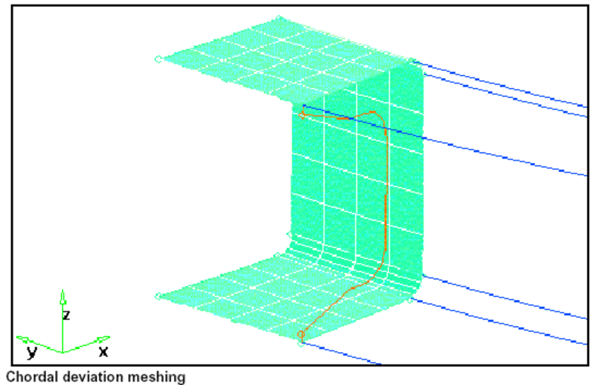
1afab965-6256-4edf-ae1d-363cf6b2e47b.png

14.点击return接受划分好的网格并返回automesh面板。

image.png

练习1.8: 理解网格参数的意义

在这个练习中,检查一个曲面上网格的参数并学习如何重新设置它们。

  • 划分网格但不改变曲面的网格参数

1.在automesh面板中选择create mesh子面板。

2.点击surfs并选择by collector。

3.选中middle和rightend这两个component collectors然后点击select。

4.将reset meshing parameters to: 选项设为无效。

5.将左上角的切换键设为elem size =。

6.点击elem size =并输入0.5。

7.将较低位置的开关设为trias。

8.点击mesh调用automeshing模块。

9.点击mesh预览网格。

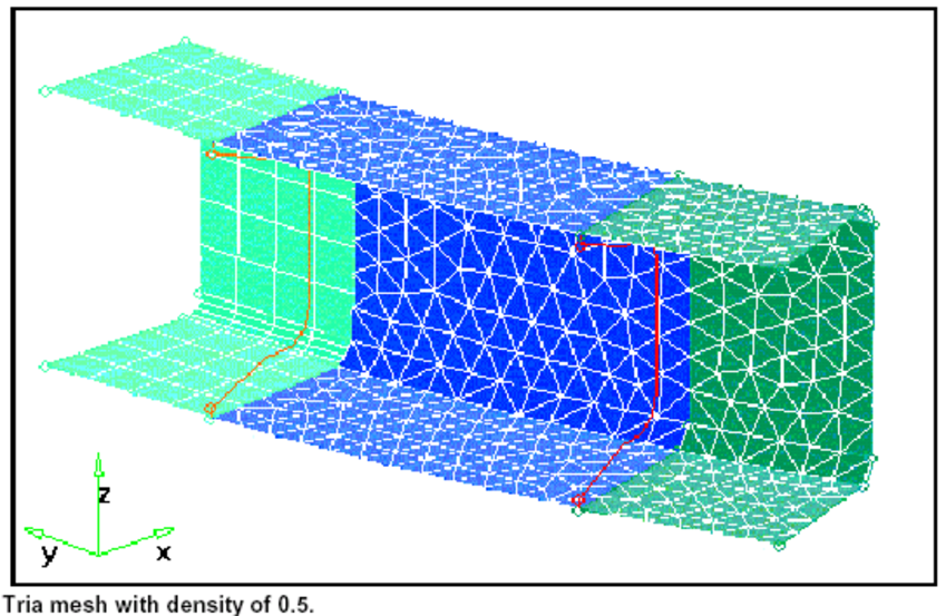
注意生成的网格与前面删除的网格是一致的,这是因为HyperMesh会为已经划分过网格的每一个曲面及其边界保存网格参数。

左端和中间component之间的曲面边界上的网格种子的分布反映了最初左端component 的网格。HyperMesh做这些工作是为了保持共享边界的单元连续性。如果想改变网格种子 的分布,在复选框中选中reset mesh parameters选项来根据指定参数重新计算节点的位置。

  • 使用details子面板查询曲面的网格参数

1.选择details子面板。

2.在右端的component中代表槽钢的支撑筋板的曲面上,点击其中心上的图标。

这会改变菜单面板上的选项,使它们与这个曲面上的网格参数设置保持一致。它在图形区中显示出单元的密度,并更新了菜单区域中的单元类型和算法。为了确定这些改变,接下来检查bias的设定。

3.将切换开关设为biases并确认沿着筋的偏移是3.0,这与在练习1.5中设置的值是一样的。

4.点击abort 退出automesh模块并返回automesh面板,但不保留网格。

  • 重新设置曲面的网格参数并重新划分网格

1.选择middle和rightend两个component中的所有曲面。

2.重新激活选项reset meshing parameters to。

3.点击mesh调用automeshing模块。

4.点击mesh预览网格。

注意到所有曲面和边的网格参数都被重新设定了,新的设定反映了0.5的单元尺寸和用三角形单元划分的规则。
9a400bdd-3cf5-48f7-8129-06445bf81070.png

5.点击return接受划分好的网格并返回automesh面板。

image.png


更多内容见附件


免责声明:

本页面/内容部分素材来源于互联网公 开 信 息,旨在传递更多信息,不代表本平台立场。

版权归原作者或机构所有,如涉及侵权,请通过平台联系我们,我们将在核实后第一时间处理。

本平台对转载内容的真实性、准确性不作任何保证,用户需自行判断并承担使用风险。

附件

免费E5-hypermesh详细划网格资料-电子书.pdf
HyperMesh
著作权归作者所有,欢迎分享,未经许可,不得转载
首次发布时间:2026-04-10
最近编辑:6月前
仿真支持爱好者
在仿真的路上越走越远
获赞 333粉丝 27文章 318课程 0
点赞
收藏
作者推荐

使用 COMSOL 5 和 MATLAB 进行多物理场建模-电子书英文版-547页

LICENSE,DISCLAIMEROFLIABILITY,ANDLIMITEDWARRANTYBypurchasingorusingthisbook(the“Work”),youagreethatthislicensegrantspermissiontousethecontentscontainedherein,butdoesnotgiveyoutherightofownershiptoanyofthetextualcontentinthebookorownershiptoanyoftheinformationorproductscontainedinit.ThislicensedoesnotpermituploadingoftheWorkontotheInternetoronanetwork(ofanykind)withoutthewrittenconsentofthePublisher.Duplicationordisseminationofanytext,code,simulations,images,etc.containedhereinislimitedtoandsubjecttolicensingtermsfortherespectiveproducts,andpermissionmustbeobtainedfromthePublisherortheownerofthecontent,etc.,inordertoreproduceornetworkanyportionofthetextualmaterial(inanymedia)thatiscontainedintheWork.MERCURYLEARNINGANDINFORMATION(“MLI”or“thePublisher”)andanyoneinvolvedinthecreation,writing,orproductionofthecompaniondisc,accompanyingalgorithms,code,orcomputerprograms(“thesoftware”),andanyaccompanyingWebsiteorsoftwareoftheWork,cannotanddonotwarranttheperformanceorresultsthatmightbeobtainedbyusingthecontentsoftheWork.Theauthor,developers,andthePublisherhaveusedtheirbesteffortstoinsuretheaccuracyandfunctionalityofthetextualmaterialand/orprogramscontainedinthispackage;we,however,makenowarrantyofanykind,expressorimplied,regardingtheperformanceofthesecontentsorprograms.TheWorkissold“asis”withoutwarranty(exceptfordefectivematerialsusedinmanufacturingthebookorduetofaultyworkmanship).Theauthor,developers,andthepublisherofanyaccompanyingcontent,andanyoneinvolvedinthecomposition,production,andmanufacturingofthisworkwillnotbeliablefordamagesofanykindarisingoutoftheuseof(ortheinabilitytouse)thealgorithms,sourcecode,computerprograms,ortextualmaterialcontainedinthispublication.Thisincludes,butisnotlimitedto,lossofrevenueorprofit,orotherincidental,physical,orconsequentialdamagesarisingoutoftheuseofthisWork.Thesoleremedyintheeventofaclaimofanykindisexpresslylimitedtoreplacementofthebook,andonlyatthediscretionofthePublisher.Theuseof“impliedwarranty”andcertain“exclusions”varyfromstatetostate,andmightnotapplytothepurchaserofthisproduct.MULTIPHYSICSMODELINGUsingCOMSOL®5andMATLAB®RogerW.Pryor,PhDCopyright©2016byMERCURYLEARNINGANDINFORMATIONLLC.Allrightsreserved.Thispublication,portionsofit,oranyaccompanyingsoftwaremaynotbereproducedinanyway,storedinaretrievalsystemofanytype,ortransmittedbyanymeans,media,electronicdisplayormechanicaldisplay,including,butnotlimitedto,photocopy,recording,Internetpostings,orscanning,withoutpriorpermissioninwritingfromthepublisher.Publisher:DavidPallaiMERCURYLEARNINGANDINFORMATION22841QuicksilverDriveDulles,VA20166info@merclearning.comwww.merclearning.com(800)232-0223RogerW.Pryor.MultiphysicsModelingUsingCOMSOL®5andMATLAB®ISBN:978-1-938549-98-4Thepublisherrecognizesandrespectsallmarksusedbycompanies,manufacturers,anddevelopersasameanstodistinguishtheirproducts.Allbrandnamesandproductnamesmentionedinthisbookaretrademarksorservicemarksoftheirrespectivecompanies.Anyomissionormisuse(ofanykind)ofservicemarksortrademarks,etc.isnotanattempttoinfringeonthepropertyofothers.LibraryofCongressControlNumber:2015910193151617321Thisbookisprintedonacid-freepaper.Ourtitlesareavailableforadoption,license,orbulkpurchasebyinstitutions,corporations,etc.Foradditionalinformation,pleasecontacttheCustomerServiceDept.at800-232-0223(tollfree).Allofourtitlesareavailableindigitalformatatauthorcloudware.comandotherdigitalvendors.Companionfiles(figuresandcodelistings)forthistitleareavailablebycontactinginfo@merclearning.com.ThesoleobligationofMERCURYLEARNINGANDINFORMATIONtothepurchaseristoreplacethedisc,basedondefectivematerialsorfaultyworkmanship,butnotbasedontheoperationorfunctionalityoftheproduct.CONTENTSPrefaceIntroductionChapter1ModelingMethodologyUsingCOMSOLMultiphysics5.xGuidelinesforNewCOMSOLMultiphysics5.xModelersHardwareConsiderationsSimpleModelSetupOverviewBasicProblemFormulationandImplicitAssumptions1DWindowHeatFlowModels1D1PaneWindowHeatFlowModel1D2PaneWindowHeatFlowModel1D3PaneWindowHeatFlowModelFirstPrinciplesasAppliedtoModelDefinitionSomeCommonSourcesofModelingErrorsReferencesSuggestedModelingExercisesChapter2MaterialsPropertiesUsingCOMSOLMultiphysics5.xMaterialsPropertiesGuidelinesandConsiderationsCOMSOLMaterialsPropertiesSourcesOtherMaterialsPropertiesSourcesMaterialPropertyEntryTechniquesMultipaneWindowModelSetBoundaryConditionsReferencesChapter30DElectricalCircuitInterfaceModelingUsingCOMSOLMultiphysics5.xGuidelinesforElectricalCircuitInterfaceModelingin5.xElectrical/ElectronicCircuitConsiderationsSimpleElectricalCircuitInterfaceModelSetupOverviewBasicProblemFormulationandImplicitAssumptions0DBasicCircuitModels0DResistor-CapacitorSeriesCircuitModel0DInductor-ResistorSeriesCircuitModel0DSeries-ResistorParallel-Inductor-CapacitorCircuitModel0DBasicCircuitModelsAnalysisandConclusionsFirstPrinciplesasAppliedto0DModelDefinitionReferencesSuggestedModelingExercisesChapter41DModelingUsingCOMSOLMultiphysics5.xGuidelinesfor1DModelingin5.x1DModelingConsiderations1DBasicModels1DKdVEquationModel1DTelegraphEquationModel1DTelegraphEquationModelSummaryandConclusions1DSphericallySymmetricTransportModel1DSphericallySymmetricTransportModelAnimationFirstPrinciplesasAppliedto1DModelDefinitionReferencesSuggestedModelingExercisesChapter52DModelingUsingCOMSOLMultiphysics5.xGuidelinesfor2DModelingin5.x2DModelingConsiderations2DBasicModels2DElectrochemicalPolishingModel2DHallEffectModelFirstPrinciplesasAppliedto2DModelDefinitionReferencesSuggestedModelingExercisesChapter62DAxisymmetricModelingUsingCOMSOLMultiphysics5.xGuidelinesfor2DAxisymmetricModelingin5.x2DAxisymmetricModelingConsiderations2DAxisymmetricHeatConductioninaCylinderModel2DAxisymmetricBasicModels2DAxisymmetricCylinderConductionModel2DAxisymmetricTransientHeatTransferModelFirstPrinciplesasAppliedto2DAxisymmetricModelDefinitionReferencesSuggestedModelingExercisesChapter72DSimpleMixedModeModelingUsingCOMSOLMultiphysics5.xGuidelinesfor2DSimpleMixedModeModelingin5.x2DSimpleMixedModeModelingConsiderations2DSimpleMixedModeModels2DElectricImpedanceSensorModel2DMetalLayeronaDielectricBlockModelHeatTransfer2(ht2)InterfaceFirstPrinciplesasAppliedto2DSimpleMixedModeModelDefinitionReferencesSuggestedModelingExercisesChapter82DComplexMixedModeModelingUsingCOMSOLMultiphysics5.xGuidelinesfor2DComplexMixedModeModelingin5.x2DComplexMixedModeModelingConsiderations2DComplexMixedModeModels2DCopperElectroplatingModel2DCopperElectroplatingModelSummaryandConclusions2DElectrocoalescenceOil/WaterSeparationModelTime-DependentSolver22DElectrocoalescenceOil/WaterSeparationModelSummaryandConclusionsFirstPrinciplesasAppliedto2DComplexMixedModeModelDefinitionReferencesSuggestedModelingExercisesChapter93DModelingUsingCOMSOLMultiphysics5.xGuidelinesfor3DModelingin5.x3DModelingConsiderations3DModels3DSpiralCoilMicroinductorModel3DSpiralCoilMicroinductorModelSummaryandConclusions3DLinearMicroresistorBeamModelMultiphysicsThermalLinearElastic1(te1).HeatTransferinSolids(ht).FirstPrinciplesasAppliedto3DModelDefinitionReferencesSuggestedModelingExercisesChapter10PerfectlyMatchedLayerModelsUsingCOMSOLMultiphysics5.xGuidelinesforPerfectlyMatchedLayer(PML)Modelingin5.xPerfectlyMatchedLayer(PML)ModelingGuidelinesandCoordinateConsiderationsPerfectlyMatchedLayerModelsBuildingthe2DConcaveMetallicMirrorPMLModelBuildingthe2DEnergyConcentratorPMLModelFirstPrinciplesasAppliedtoPMLModelDefinitionReferencesSuggestedModelingExercisesChapter11BioheatModelsUsingCOMSOLMultiphysics5.xGuidelinesforBioheatModelingin5.xBioheatModelingConsiderationsBioheatTransferModels2DAxisymmetricMicrowaveCancerTherapyModelFirstPrinciplesasAppliedtoBioheatModelDefinitionReferencesSuggestedModelingExercisesAppendixABriefIntroductiontoLiveLinkTMforMATLAB®A.AppendixABriefIntroductiontoCOMSOLApplicationBuilderB.IndexPREFACEThepurposeofthisbookistointroducehands-onmodelbuildingandsolvingwithCOMSOLMultiphysics®softwareversion5toscientists,engineers,andotherpersonsinterestedinexploringthebehaviorofphysicaldevicestructuresbuiltonacomputer(avirtualprototype),beforegoingtotheworkshoporlaboratoryandtryingtobuildthewhatever-it-is(arealprototype).Themodelspresentedhereinarebuiltwithinthecontextofthelawsofthephysicalworld(appliedphysics)andareexploredinlightofFirstPrincipleAnalysistechniques.Aswithanyothermethodofproblem-solution,theinformationobtainedthroughtheuseofsolutionstothesecomputersimulations(virtualprototypes)isonlyasaccurateasthematerialsproperties’valuesandthefundamentalassumptionsemployedtobuildthesesimulations.Theprimaryadvantageofthecombinationofcomputersimulation(virtualprototyping)andFirstPrinciplesAnalysistoexploreartifacts(devicestructures)isthatthemodelercantryasmanydifferentapproachestothesolutionofthesameunderlyingproblemasareneededinordertogetitright(orclosethereto)forthefirsttime,beforefabricationofthedevicecomponentsandtheassembleddevice(realprototype)intheworkshoporlaboratory.ACKNOWLEDGMENTSIwouldliketothankDavidPallaiofMercuryLearningandInformationforhisongoingencouragement.IwouldalsoliketothankthemanystaffmembersofCOMSOL,Inc.fortheirhelpandencouragement.IwouldespeciallyliketothankBeverlyE.Pryor,mywife,forherpatienceandencouragementduringthecreationofthemanuscriptofthisbook.Anyresidualerrorsinthisworkaremineandminealone.RogerW.Pryor,PhDJuly2015INTRODUCTIONCOMSOLMultiphysicssoftwareisapowerfulFiniteElement(FEM),PartialDifferentialEquation(PDE)solutionengine.ThebasicCOMSOLMultiphysics5.xsoftwarehasovertwentyfive(25)add-onmodulesthatexpandthecapabilitiesofthebasicsoftwareintoabroadcollectionofapplicationareas:AC/DC,Acoustics,BatteriesandFuelCells,CFD,ChemicalReactionEngineering,Electrodeposition,Geomechanics,HeatTransfer,MEMS,Microfluidics,Plasma,RF,StructuralMechanicsandSubsurfaceFlow,tonameafew.TheCOMSOLMultiphysicssoftwarealsohasothersupportingsoftware,suchas:theOptimizationModule,theMaterialLibraryModule,theCADImportModuleandLiveLink™interfacesforseveralengineeringsoftwareprograms.Inthisbook,scientists,engineers,andothersinterestedinexploringthebehaviorofdifferentphysicaldevicestructuresthroughcomputermodelingareintroducedtothetechniquesofhands-onbuildingandsolvingmodelsthroughthedirectapplicationofthebasicCOMSOLMultiphysicssoftware,alongwithsomesamplesusingtheAC/DC,ChemicalReactionEngineering,HeatTransfer,MEMS,andRFmodules.ThenexttothelasttechnicalchapterexplorestheuseofPerfectlyMatchedLayersintheRFModule.ThefinaltechnicalchapterexplorestheuseoftheBioheatEquationintheHeatTransferandRFModules.Themodelspresentedhereinarebuiltwithinthecontextofthephysicalworld(appliedphysics)andarepresentedinlightofFirstPrincipleAnalysistechniques.Thedemonstrationmodelsemphasizethefundamentalconceptthattheinformationderivedfromthemodelingsolutionsthroughuseofthesecomputersimulationsisonlyasgoodasthematerialscoefficientsandthefundamentalassumptionsemployedinbuildingthemodels.ThecombinationofcomputersimulationandFirstPrinciplesAnalysisgivesthemodelertheopportunitytotryavarietyofapproachestothesolutionofthesameproblemasneededinordertogetthedesignrightornearlyrightintheworkshoporlaboratorybeforethefirstdevicecomponentsarefabricatedandtested.Themodelercanalsousethephysicaldevicetestresultstomodifythemodelparametersandarriveatanimprovedsolutionmorerapidlythanbysimplyusingthecutandtrymethodology.CHAPTERTOPICSTheeleven(11)technicalchaptersinthisbookdemonstratetothereaderthehandsontechniqueofmodelbuildingandsolving.TheCOMSOLconceptsandtechniquesusedinthesechaptersareshowninFigureInt.1.FIGUREINT.1COMSOLConceptsandtechniquesTheCOMSOLmodulesemployedinthevariousmodelsinspecificchaptersareshowninFigureInt.2,andthephysicsconceptsandtechniquesemployedinthevariousmodelsinspecificchaptersareshowninFigureInt.3.FIGUREINT.2COMSOLModulesemployedFIGUREINT.3PhysicsConceptsandtechniquesTheinformationinthesethreefigureslinktheoverallpresentationofthisbooktotheunderlyingmodeling,mathematical,andphysicalconcepts.Inthisbook,incontrasttosomeotherbookswithwhichthereadermaybefamiliar,keyancillaryinformationis,inmostcases,containedinthenotes.NOTEPleasebesuretoread,carefullyconsider,andapply,asneeded,eachnote.CHAPTER1.MODELINGMETHODOLOGYChapter1providesanoverviewofthemodelingprocessbydiscussingthefundamentalconsiderationsinvolved:thehardware(computerplatform),thecoordinatesystems(physics),theimplicitassumptions(lowerdimensionalityconsiderations),andFirstPrinciplesAnalysis(physics).Threerelativelysimple1Dmodelsarepresentedthatbuildandsolve,forcomparison,single-,double-,andtriple-panethermalinsulationwindowstructures.Commentsarealsoincludedoncommonsourcesofmodelingerrors.CHAPTER2.MATERIALSPROPERTIESChapter2discussesvarioussourcesofmaterialspropertiesdata,includingtheCOMSOLMaterialLibrary,basicandexpandedmodule,aswellasprintandInternetsources.Amulti-panelthermalinsulationwindowstructuremodeldemonstratesthreetechniquesforenteringmaterialproperties:user-defineddirectentry,user-definedparameters,andmaterialdefinitions.AlsoincludedareinstructionsforbuildingauserdefinedmateriallibraryforstoragewithinCOMSOL5.x.CHAPTER3.0DELECTRICALCIRCUITINTERFACECOMSOL5.xuseszero-dimensionalmodelstoprovideforthemodelingofelectricalcircuitry.Themodelsinthischapterillustratetechniquesformodelingvariousbasiccircuits:aresistor-capacitorseriescircuit,aninductor-resistorseriescircuit,andaseriesresistor,parallelinductor-capacitorcircuit.ConsiderationsforthepropersetupofthecircuitsarediscussedalongwiththebasicsofproblemformulationandtheimplicitassumptionsbuiltintoCOMSOL5.xrelativetoelectricalcircuitmodeling.CHAPTER4.1DMODELINGThefirstpartofChapter4modelsthe1DKdVEquation.TheKdVEquationisapowerfultoolthatisusedtomodelsolitonwavepropagationindiversemedia(e.g.physicalwavesinliquids,electromagneticwavesintransparentmedia,etc.).Itiseasilyandsimplymodeledwitha1DPDEmodemodel.ThesecondpartofChapter4modelsthe1DTelegraphEquation.TheTelegraphEquationisapowerfultoolthatisusedtomodelwavepropagationindiversetransmissionlines.TheTelegraphEquationcanbeusedtothoroughlycharacterizethepropagationconditionsofcoaxiallines,twinpairlines,microstriplines,etc.TheTelegraphEquationiseasilyandsimplymodeledwitha1DPDEmodemodel.ThelastpartofChapter4isa1DSphericallySymmetricTransportmodelthatillustratesthetechniqueofsimplifyingmodelswithsphericalcomponentsfrom3Dto1Dbyassumingthattheyareessentiallysymmetrical.更多内容见附件免责声明:本页面/内容部分素材来源于互联网公开信息,旨在传递更多信息,不代表本平台立场。版权归原作者或机构所有,如涉及侵权,请通过平台联系我们,我们将在核实后第一时间处理。本平台对转载内容的真实性、准确性不作任何保证,用户需自行判断并承担使用风险。
有附件
未登录
还没有评论
课程
培训
服务
行家
VIP会员 学习计划 福利任务
下载APP
联系我们
帮助与反馈