AtlasofStress-StrainCurvesSecondEditionCopyright◎2002byASMInternational®AllnightsreservedNopartofthisbookmaybereproduced,storedinaretrievalsystem,ortransmitted,inanyformorbyanymeans,electronic,mechanical,photocopying,recording,orotherwise,withoutthewrittenpermissionofthecopyrightowner.Firstprinting,December2002Greatcareistakeninthecompilationandproductionofthisbook,butitshouldbemadeclearthatNOWARRANTIES,EXPRESSORIMPLIED,INCLUDING,WITHOUTLIMITATION,WARRANTIESOFMERCHANTABILITYORFITNESSFORAPARTICULARPURPOSE,AREGIVENINCONNECTIONWITHTHISPUBLICATION.AIthoughthisinformationisbelievedtobeaccuratebyASM,ASMcannotguaranteethatfavorableresultswillbeobtainedfromtheuseofthispublicationalone.Thispubli-cationisintendedforusebypersonshavingtechnicalskill,attheirsolediscretionandrisk.SincetheconditionsofproductormaterialuseareoutsideofASM'scontrol,ASMassumesnoliabilityorobligationinconnectionwithanyuseofthisinformation.Noclaimofanykind,whetherastoproductsorinformationinthispublication,andwhetherornotbasedonnegligence,shallbegreaterinamountthanthepurchasepriceofthisproductorpublicationinrespectofwhichdamagesareclaimed.THEREMEDYHEREBYPROVIDEDSHALLBETHEEXCLUSIVEANDSOLEREMEDYOFBUYER,ANDINNOEVENTSHALLEITHERPARTYBELIABLEFORSPECIAL,INDIRECTORCONSEQUENTIALDAMAGESWHETHERORNOTCAUSEDBYORRESULTINGFROMTHENEGLIGENCEOFSUCHPARTY.Aswithanymaterial,evaluationofthematerialunderend-useconditionspriortospecificationisessential.Therefore,specifictestingunderactualconditionsisrecommended.Nothingcontainedinthisbookshallbeconstruedasagrantofanyrightofmanufacture,sale,use,orreproduction,incon-nectionwithanymethod,process,apparatus,product,composition,orsystem,whetherornotcoveredbyleterspatent,copyright,ortrademark,andnothingcontainedinthisbookshallbeconstruedasadefenseagainstanyallegedinfringementofletterspatent,copy-right,ortrademark,orasadefenseagainstliabilityforsuchinfringement.Comments,criticisms,andsuggestionsareinvited,andshouldbeforwardedtoASMInternational.PreparedunderthedirectionoftheASMInternationalTechrnicalBookCommittee(2001-2002),CharlesA.Parker,Chair:PreparedwithassistancefromtheASMInternationalMaterialsPropertiesDatabaseCommittee,PJ.Sikorsky,Chair.ASMInternationalstaffwhoworkedonthisprojectincludedCharlesMoosbrugger,TechnicalEditor;VeronicaFlint,AcquisitionsEditor;BonnieSanders,ManagerofProduction;CarolTerman,ProductionProjectManager;andScotHenry,AssistantDirectorofReferencePublications.LibraryofCongressCataloging-in-PublicationDataAtlasofstress-straincurves.—2nded.p.cm.SAN:204-586—T.p.verso.ISBN:0-87170-739-X1.Stress-straincurves—Atlases.2.Metals—Testing.I.ASMInternational.TA460.A862002620.1'63—dc212002027674ASMInternational®MaterialsPark,OH44073-0002www.asminternationalorgPrintedintheUnitedStatesofAmericaContentsPreface........................................................................................................................................ivRepresentationofStress-StrainBehavior..................................................................1FerrousMetals....................................................................................................................21CastIron(CI)........................................................................................................................23CarbonSteel(CS)..............................................................................................................67AlloySteel(AS)..................................................................................................................93High-StrengthSteel(HS).............................................................................................129StainlessSteel(SS).........................................................................................................161ToolSteel(TS)...................................................................................................................269NonferrousMetals.........................................................................................................277CastAluminum(CA)......................................................................................................279WroughtAluminum(WA)............................................................................................299AluminumLaminates(LA).........................................................................................503Copper(Cu)..........................................................................................................................515Magnesium(Mg)...............................................................................................................555Nickel(Ni)...........................................................................................................................631ReactiveandRefractoryMetals(RM)................................................................705Titanium(Ti).......................................................................................................................729PureMetalsandMiscellaneousAlloys(MA)................................................799AlloyIndex..................................................................................................................809UNSIndex........................................................................................................................815PrefaceInthisinformationage,mechanicalpropertydataareplentiful.However,locatingneededinformationquickly,judgingthevalidityofthedata,andmakingreasonedcomparisonsofdatacanbedaunting.Stress-straincurvescondensemuchinformationaboutthemechanicalbehaviorofmetalsintoaconvenientform.Fromthesebasiccurvestheengineercanextractsuchinformationasthestrength,ductility,forma-bility,elasticity,andotherinformationusefulinpredictingtheper-formanceofaparticularalloyunderstress.ASMInternationalpublishedthefirsteditionoftheAtlasofStress-StrainCurves,acollectionofover550curves,in1986.Thisbook,alongwiththeAtlasofFatigueCurves,AtlasofCreepandStress-RuptureCurves,andtheAtlasofStress-CorrosionandCorrosionFatigueCurves,hasformedasetofusefulmaterialspropertyresourcesfortheengineer,materialsscientist,anddesigner.Welloverthreeyearsago—withtheencouragement,assistance,andguidanceoftheASMTechnicalBooksandMaterialsPropertiesDatabaseCommittees—ASMInternationalembarkedontheprojecttocreatethisupdated,expanded,andimprovedSecondEditionoftheAtlasofStress-StrainCurves.Someoftheoverridinggoalsofthisprojecthavebeento:●Addcurvesformaterialsthatareespeciallyusefultokeyindustries,includingaerospace,automotive,andheavymanufacturingSeekoutcurveswitha“pedigree”soreaderscantracethesourceoftheinformationandhavesomeindicationregardingitsreliability●Includeasmuchpertinentinformationaspossibleforeachcurve.Factorssuchasheat-treatcondition,productform,thickness,spec-imensize,orientation,history,testingtemperature,andtestingrateallaffectmaterialsperformanceandmaybehelpfulwheninter-pretingthecurves●NormalizethepresentationofthecurvestofacilitatecomparisonsamongdifferentmaterialsWefeelASMInternationalhasbeenreasonablysuccessfulinachievingtheseobjectivesinthiseditin.Manypeopleareinvolvedinaprojectofthissize,andwewouldliketothankthosewhohavecontributedto,orassisted,thiseffortFirstandforemost,ASMInternationalthanksthematerialsresearcherswhocreatedtheoriginalcurves--withouttheireffortsthisvolumewouldnotexist.DonnaM.Walker,FASM,StressolversInc.,andVeronicaFlint,ASMstaff,initiatedtheprojecttoreviseandexpandthisbook.ASMInternationalthanksthemfortheireffortsinhelpingtodefinethegoalsforthisprojectandinacquiringmanyofthenewcurvestobeaddedtothebook.SpecialthanksareextendedtoSpecialMetals,GilKaufman,FASM,KaufmanAssociates,andBuceBoardman,FASM,Deere&Company,fortheircontributionsofstress-straincurves.HiroOkamotoandhisassociatesperformedthehugetaskofredrawingthecurvestonormalizetheirpresentation,andwearegrate-fulfortheiraccurateandtimelywork.Theorganizationandfinalqualityofthedataasseeninthebookaremyresponsibility,andanyerrors,omissions,ormisclassificationsofalloysaremine.IthankHeatherLampman,theprincipalcopyedi-tor,andthemembersoftheASMInternationalproductionstaff,whohaveworkeddiligentlytokeepanyerrorstoaminimum.However,inanyendeavorofthisscope,therewillbemistakes.Corrections,com-ments,andcriticismsareinvited.Itshouldbenotedthatmostofthedataincludedinthisbookarenotspecifiedasbeingminimum,typical,orhavinganydefinedconfi-dencelevelassociatedwiththem.Thereadermaywanttorefertothesourceofaparticularcurvetofindadditionaldetails.The"Introduction"inthisbookprovidesareviewoftheinformationthatcanbeextractedfromstress-straincurves,aclarificationoftermsusedindescribingmechanicalbehavior,andaguidetothelimitationsoftheaccuracyandprecisionoftheinformationgiven.CharlesMoosbruggerTechnicalEditorASMInternationalRepresentationofStress-StrainBehaviorCharlesMoosbrugger,ASMInternationalITISAPPROPRIATEthatacollectionofstress-straincurvesisnamedanatlas.Anatlasisacollectionoffigures,charts,ormaps,SonamedbecauseearlybookspicturedtheGreekTitan,Atlas,onthecoverortitlepage,strainingwiththeweightoftheworldandheavensonhisshoulders.Thisconceptofvisualizingthereactiontomechani-calstressiscentraltodevelopmentanduseofstress-straincurves.Thisintroductorysectionprovidesareviewofthefundamentalsofthemechanicaltestingthatisrepresentedinthecurves.Themathemat-icalinterpretationofaspectsofthecurveswillaidinanalysisofthecurves.Alistoftermscommontostress-strainbehaviorisgivenattheendofthissection.(Ref1,2).TensileTestingThesimplestloadingtovisualizeisaone-dimensionaltensiletest,inwhichauniformslendertestspecimenisstretchedalongitslongcen-tralaxis.Thestress-straincurveisarepresentationoftheperformanceofthespecimenastheappliedloadisincreasedmonotonicallyusuallytofracture.Stress-straincurvesareusuallypresentedas:●“Engineering”stress-straincurves,inwhichtheoriginaldimensionsofthespecimensareusedinmostcalculations.●"True"stress-straincurves,wheretheinstantaneousdimensionsofthespecimenateachpointduringthetestareusedinthecalcula-tions.Thisresultsinthe“true”curvesbeingabovethe“engineer-ing”curves,notablyinthehigherstrainportionofthecurves.Thedevelopmentofthesecurvesisdescribedinthefollowingsec-tions.Todocumentthetensiontest,anengineeringstress-straincurveisconstructedfromtheload-elongationmeasurementsmadeonthetestspecimen(Fig.1).Theengineeringstress,S,plottedonthisstress-straincurveistheaveragelongitudinalstressinthetensilespecimen.Fig.1Engineeringstress-straincurve.Intersectionofthedashedlinewiththecurvedeterminestheoffsetyieldstrength.Itisobtainedbydividingtheload,P,bytheoriginalareaofthecrosssec-tionofthespecimen,Ao:Thestrain,e,plottedontheengineeringstress-straincurve,istheaver-agelinearstrain,whichisobtainedbydividingtheelongationofthegagelengthofthespecimen,δ,byitsoriginallength,Lo:Becauseboththestressandthestrainareobtainedbydividingtheloadandelongationbyconstantfactors,theload-elongationcurvehasthesameshapeastheengineeringstress-straincurve.Thetwocurvesfre-quentlyareusedinterchangeably.Theunitsofstressareforce/lengthsquared,andthestrainisunitless.Thestrainaxisofcurvestraditionallyaregivenunitsofin./in.ormm/mmratherthanbeinglistedasapurenumber.Strainissometimesexpressedasapercentelongation.Theshapeofthestress-straincurveandvaluesassignedtothepointsonthestress-straincurveofametaldependonits:●Composition●Heattreatmentandconditioning●Priorhistoryofplasticdeformation●Thestrainrateoftest●Temperature●Orientationofappliedstressrelativetothetestspecimensstructure●SizeandshapeTheparametersthatareusedtodescribethestress-straincurveofametalarethetensilestrength,yieldstrengthoryieldpoint,ultimateten-silestrength,percentelongation,andreductioninarea.Thefirstthreearestrengthparameters;thelasttwoindicateductility.Thegeneralshapeoftheengineeringstress-straincurve(Fig.1)requiresfurtherexplanation.Thiscurverepresentsthefullloadingofaspecimenfrominitialloadtorupture.Itisa“full-range”curve.Oftenengineeringcurvesaretruncatedpastthe0.2%yieldpoint.ThisisthecaseofmanyofthecurvesinthisAtlas.Othertestdataarepresentedasa“full-range”curvewithan“expandedrange”todetailtheinitialpartsofthecurve.LinearSegmentofCurvesFromtheorigin,0,theinitialstraight-lineportionistheelasticregion,wherestressislinearlyproportionaltostrain.Whenthestressisremoved,ifthestraindisappears,thespecimenisconsideredcom-pletelyelastic.Thepointatwhichthecurvedepartsfromthestraight-linepropor-tionality,A,istheproportionallimit.Modulusofelasticity,E,alsoknownasYoung'smodulus,istheslopeofthisinitiallinearportionofthestress-straincurve:whereSisengineeringstressandseisengineeringstrain.Modulusofelasticityisameasureofthestiffnessofthematerial.Thegreaterthemodulus,thesteepertheslopeandthesmallertheelasticstrainresult-ingfromtheapplicationofagivenstress.Becausethemodulusofelas-ticityisneededforcomputingdeflectionsofbeamsandotherstructuralmembers,itisanimportantdesignvalue.Themodulusofelasticityisdeterminedbythebindingforcesbetweenatoms.Becausetheseforcescannotbechangedwithoutchangingthebasicnatureofthematerial,themodulusofelasticityisoneofthemoststructure-insensitiveofthemechanicalproperties.Generally,itisonlyslightlyaffectedbyalloyingadditions,heattreat-ment,orcoldwork(Ref3).However,increasingthetemperaturedecreasesthemodulusofelasticity.Atelevatedtemperatures,themod-ulusisoftenmeasuredbyadynamicmethod(Ref4).TypicalvaluesofmodulusofelasticityforcommonengineeringmaterialsaregiveninTable1(Ref5).Resilienceistheabilityofamaterialtoabsorbenergywhendeformedelasticallyandtoreturnitwhenunloaded.Thispropertyusu-allyismeasuredbythemodulusofresilience,whichisthestrainenergyperunitvolume,Uo,requiredtostressthematerialfromzerostresstotheyieldstress,Sx.Thestrainenergyperunitvolumeforanypointonthelineisjusttheareaunderthecurve:Fromthedefinitionofmodulusofelasticityandtheabovedefinition,themaximumresilienceoccursattheyieldpointandiscalledthemod-ulusofresilience,UR:Thisequationindicatesthattheidealmaterialforresistingenergyloadsinapplicationswherethematerialmustnotundergopermanentdistor-Table1TypicalvaluesformodulusofelasticityFig.2Stress-straincurvesforselectedsteels.Source:Ref7tion,suchasmechanicalsprings,isonehavingahighyieldstressandalowmodulusofelasticity.Forvariousgradesofsteel,themodulusofresiliencerangesfrom100to4500kJ/m³(14.5to6501bf·in./in.³),withthehighervaluesrep-resentingsteelswithhighercarbonoralloycontents(Ref6).ThiscanbeseeninFig.2,wherethemodulusofresilienceforthechromium-tungstenalloywouldbethegreatestofthesteels,becauseithasthehighestyieldstrengthandsimilarmodulusofelasticity.ThemodulusofresilienceisrepresentedasthetriangularareasunderthecurvesinFig.3.Figure2showsthatwhilethemodulusofelasticityisconsistentforthegivengroupofsteels,theshapesofthecurvespasttheirpropor-tionalitylimitsarequitevaried(Ref7)Fig.3Comparisonofstress-straincurvesforahigh-strengthhigh-carbonspringsteelandalower-strengthstructuralsteel.PointAistheelasticlimitofthespringsteel;pointBistheelasticlimitofthestructuralsteel.Thecross-hatchedtrian-glesarethemodulusofresilience(UR).Thesetwoareasaretheworkdoneonthematerialstoelongatethemortherestoringforcewithinthematerials.NonlinearSegmentofCurvestoYieldingTheelasticlimit,B,onFig.1,maycoincidewiththeproportional-itylimit,oritmayoccuratsomegreaterstress.Theelasticlimitisthemaximumstressthatcanbeappliedwithoutpermanentdeformationtothespecimen.Somecurvesexhibitadefiniteyieldpoint,whileothersdonot.Whenthestressexceedsavaluecorrespondingtotheyieldstrength,thespecimenundergoesgrossplasticdeformation.Iftheloadissubsequentlyreducedto0,thespecimenwillremainpermanentlydeformed.MeasuresofYielding.Thestressatwhichplasticdeformationoryieldingisobservedtobegindependsonthesensitivityofthestrainmeasurements.Withmostmaterials,thereisagradualtransitionfromelastictoplasticbehavior,andthepointatwhichplasticdeformationbeginsisdifficulttodefinewithprecision.Intestsofmaterialsunderuniaxialloading,threecriteriafortheinitiationofyieldinghavebeenused:theelasticlimit,theproportionallimit,andtheyieldstrength.Elasticlimit,shownatpointBinFig.1,isthegreateststressthematerialcanwithstandwithoutanymeasurablepermanentstrainremainingafterthecompletereleaseofload.Withincreasingsensitiv-ityofstrainmeasurement,thevalueoftheelasticlimitisdecreaseduntilitequalsthetrueelasticlimitdeterminedfrommicrostrainmeas-urements.Withthesensitivityofstraintypicallyusedinengineeringstudies(10-4mm/mmorin./in.),theelasticlimitisgreaterthanthepro-portionallimit.Determinationoftheelasticlimitrequiresatediousincrementalloading-unloadingtestprocedure.Forthisreason,itisoftenreplacedbytheproportionallimit.Theyieldstrength,shownatpointYSinFig.1,isthestressrequiredtoproduceasmallspecifiedarnountofplasticdeformation.Theusualdefinitionofthispropertyistheoffsetyieldstrengthdeterminedbythestresscorrespondingtotheintersectionofthestress-straincurveoffsetbyaspecifiedstrain(seeFig.1).IntheUnitedStates,theoffsetisusu-allyspecifiedasastrainof0.2%or0.1%(e=0.002or0.001).Offsetyieldstrengthdeterminationrequiresaspecimenthathasbeenloadedtoits0.2%offsetyieldstrengthandunloadedsothatitis0.2%longerthanbeforethetest.TheoffsetyieldstrengthisreferredtoinISOStandardsastheproofstress(Rpo,1orRpo,2).IntheENstandardsformaterialsthatdonothaveayieldphenomenonpresent,the0,2%proofstrength(Rpo,2)or0,5%(Rpo,5)isdetermined.Thenonpropor-tionalelongationiseither0.1%,0.2%,or0.5%.Theyieldstrengthobtainedbyanoffsetmethodiscommonlyusedfordesignandspeci-ficationpurposes,becauseitavoidsthepracticaldifficultiesofmeasur-ingtheelasticlimitorproportionallimit.Somematerialshaveessentiallynolinearportiontotheirstress-straincurve,forexample,softcopperorgraycastiron.Forthesemate-rials,theoffsetmethodcannotbeused,andtheusualpracticeistodefinetheyieldstrengthasthestresstoproducesometotalstrain,forexample,e=0.005.TheEuropeanStandardforgeneral-purposecop-perrod,EN12163(Ref8),givesapproximate0,2%proofstrength(Rpo,2)forinformation,butitisnotarequirement.Thisapproachisfol-lowedforothermaterialforms(barandwire),butforsomecoppertubes,amaximumRpo,2isspecifiedForcopperalloypressurevesselplateandsomespringstrip,aminimumRpo,2isspecified.MaterialswithYieldPointPhenomenon.Manymetals,particu-larlyannealedlow-carbonsteel,showalocalized,heterogeneoustypeoftransitionfromelastictoplasticdeformationthatproducesayieldpointinthestress-straincurve.Ratherthanhavingaflowcurvewithagradualtransitionfromelastictoplasticbehavior,suchasFig.4(a),metalswithayieldpointproduceaflowcurveoraload-elongationdia-gramsimilartoFig.4(b).Theloadincreasessteadilywithelasticstrain,dropssuddenly,fluctuatesaboutsomeapproximatelyconstantvalueofload,andthenriseswithfurtherstrain.Fig.4t(I)in(d)u(e)ou(aliz)s(e)yiel(dpl)din(ots)g(o)wi(fs)t(t)h(r)ean(ss)-up(str)p(a)ie(n)r.(y(a)ip(n)to(i)nint(u)oA(u)san(y)d(ie)la(d)ire(ng)lat(c)iv(o)e(n)dly(i)tco(io)nn.s(t(b)a)nt(D)iy(s)cie(o)l--ingstressBtoCInENstandardsformaterialsexhibitingayieldpoint,theupperyieldstrength,ReHmaybespecified.Theupperandloweryieldstress(ReH₃ReL)arespecifiedinsomeENandISOstandardsinunitsofN/mm²(1N/mm²=1MPa).EN10027-1(Ref9)notestheterm“yieldstrength”asusedinthisEuropeanstandardreferstoupperorloweryieldstrength(ReHorReL),proofstrength(Rp),ortheproofstrengthtotalextension(R),dependingontherequirementspecifiedintherelevantproductstandard.Thisservesasacautionthatthedetailsonhowthe“yieldstrength”or“yieldpoint”isdefinedmustbeknownwhenmakinganycomparisonsorconclusionsastothematerialscharacteristics.Typicalyieldpointbehavioroflow-carbonsteelisshowninFig.5.Theslopeoftheinitiallinearportionofthestress-straincurve,desig-natedbyE,isthemodulusofelasticity.Theloadatwhichthesuddendropoccursiscalledtheupperyieldpoint.Theconstantloadiscalledtheloweryieldpoint,andtheelongationthatoccursatconstantloadiscalledtheyield-pointelongation.Thedeformationoccurringthrough-outtheyield-pointelongationisheterogeneous.Attheupperyieldpoint,adiscretebandofdeformedmetal,oftenreadilyvisible,appearsatastressconcentrationsuchasafillet.Coincidentwiththeformationoftheband,theloaddropstotheloweryieldpoint.Thebandthenpropagatesalongthelengthofthespecimen,causingtheyield-pointelongation.Fig.5Typicalyieldpointbehavioroflow-carbonsteelIntypicalcases,severalbandsformatseveralpointsofstresscon-centration.Thesebandsaregenerallyatapproximately45°totheten-sileaxis.TheyareusuallycalledLüdersbands,Hartmannlines,orstretcherstrains,andthistypeofdeformationissometimesreferredtoasthePioberteffect.Theyarevisibleandcanbeaestheticallyundesir-able.WhenseveralLüdersbandsareformed,theflowcurveduringtheyield-pointelongationisirregular,eachjogcorrespondingtothefor-mationofanewLüdersband.AftertheLüdersbandshavepropagatedtocovertheentirelengthofthespecimentestsection,theflowwillincreasewithstraininthetypicalmanner.Thismarkstheendoftheyield-pointelongation.ThetransitionfromundeformedtodeformedmaterialattheLüdersfrontcanbeseenatlowmagnificationinFig.6.TheroughsurfaceareasaretheLüdersbandsinthelow-carbonsteel.Thesebandsarealsoformedincertainaluminum-magnesiumalloys.NonlinearSegmentofContinuedDeformationStrainHardening.Thestressrequiredtoproducecontinuedplasticdeformationincreaseswithincreasingplasticstrain;thatis,themetalstrainhardens.Thevolumeofthespecimen(area×length)remainsconstantduringplasticdeformation,AL=A₀Lo,andasthespecimenelongates,itscross-sectionalareadecreasesuniformlyalongthegagelength.Initially,thestrainhardeningmorethancompensatesforthisdecreaseinarea,andtheengineeringstress(proportionaltoloadP)continuestorisewithincreasingstrain.Eventually,apointisreachedwherethedecreaseinspecimencross-sectionalareaisgreaterthantheincreaseindeformationloadarisingfromstrainhardening.Thiscondi-tionwillbereachedfirstatsomepointinthespecimenthatisslightlyweakerthantherest.Allfurtherplasticdeformationisconcentratedinthisregion,andthespecimenbeginstoneckorthindownlocally.Thestrainuptothispointhasbeenuniform,asindicatedonFig.1.Becausethecross-sectionalareaisnowdecreasingfarmorerapidlythantheabilitytoresistthedeformationbystrainhardening,theactualloadrequiredtodeformthespecimendecreasesandtheengineeringstressdefinedinEq1continuestodecreaseuntilfractureoccurs,atX.Thetensilestrength,orultimatetensilestrength,S,isthemax-imumloaddividedbytheoriginalcross-sectionalareaofthespecimen:Thetensilestrengthisthevaluemostfrequentlyquotedfromtheresultsofatensiontest.Actually,however,itisavalueoflittlefundamentalsignificancewithregardtothestrengthofametal.Forductilemetals,thetensilestrengthshouldberegardedasameasureofthemaximumloadthatametalcanwithstandundertheveryrestrictiveconditionsofuniaxialloading.Thisvaluebearslittlerelationtotheusefulstrengthofthemetalunderthemorecomplexconditionsofstressthatusuallyareencountered.Formanyyears,itwascustomarytobasethestrengthofstructuralmembersonthetensilestrength,suitablyreducedbyafactorofsafetyThecurrenttrendistothemorerationalapproachofbasingthestaticdesignofductilemetalsontheyieldstrength.However,becauseofthelongpracticeofusingthetensilestrengthtodescribethestrengthofmaterials,ithasbecomeafamiliarproperty,andassuch,itisausefulidentificationofamaterialinthesamesensethatthechemicalcompo-sitionservestoidentifyametaloralloy.Furthermore,becausetheten-silestrengthiseasytodetermineandisareproducibleproperty,itisusefulforthepurposesofspecificationandforqualitycontrolofaproduct.Extensiveempiricalcorrelationsbetweentensilestrengthandpropertiessuchashardnessandfatiguestrengthareoftenuseful.Forbrittlematerials,thetensilestrengthisavaliddesigncriterion.MeasuresofDuctility.Currently,ductilityisconsideredaqualita-tive,subjectivepropertyofamaterial.Ingeneral,measurementsofductilityareofinterestinthreerespects(Ref10):●Toindicatetheextenttowhichametalcanbedeformedwithoutfractureinmetalworkingoperationssuchasrollingandextrusion●Toindicatetothedesignertheabilityofthemetaltoflowplasticallybeforefracture.Ahighductilityindicatesthatthematerialis“for-giving”andlikelytodeformlocallywithoutfractureshouldthede-signererrinthestresscalculationorthepredictionofsevereloads.Toserveasanindicatorofchangesinimpuritylevelorprocessingconditions.Ductilitymeasurementsmaybespecifiedtoassessma-terialquality,eventhoughnodirectrelationshipexistsbetweentheductilitymeasurementandperformanceinservice.Theconventionalmeasuresofductilitythatareobtainedfromthetensiontestaretheengineeringstrainatfracture,es,(usuallycalledtheelongation)andthereductioninareaatfracture,q.Elongationandreductioninareausuallyareexpressedasapercentage.Bothofthesepropertiesareobtainedafterfracturebyputtingthespecimenbacktogetherandtakingmeasurementsofthefinallength,Lf,andfinalspec-imencrosssection,Af:Becauseanappreciablefractionoftheplasticdeformationwillbeconcentratedintheneckedregionofthetensionspecimen,thevalueofefwilldependonthegagelengthLooverwhichthemeasurementwastaken(seethesectionofthisarticleonductilitymeasurementintensiontesting).Thesmallerthegagelength,thegreaterthecontributiontotheoveralelongationfromtheneckedregionandthehigherthevalueofer.Therefore,whenreportingvaluesofpercentageelongation,thegagelength,Lo,shouldalwaysbegiven.Reductioninareadoesnotsufferfromthisdifficulty.Thesevaluescanbeconvertedintoanequivalentzero-gage-lengthelongation,eoFromtheconstancyofvolumerelationshipforplasticdeformation(AL=A₀Lo):更多内容见附件免责声明:本页面/内容部分素材来源于互联网公开信息,旨在传递更多信息,不代表本平台立场。版权归原作者或机构所有,如涉及侵权,请通过平台联系我们,我们将在核实后第一时间处理。本平台对转载内容的真实性、准确性不作任何保证,用户需自行判断并承担使用风险。






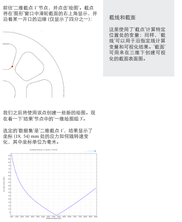

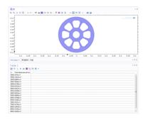
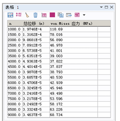
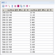
 并选择'结构力学' > '应力' > 'von Mises 应力 (solid.mises)'。更改单位为 Mpa 并点击'计算'。