MeshFree|结构快速仿真技术在无人机设备中的应用研究
Abstract:
With advances in drone technology, various drone applications have been proposed in areas such as reconnaissance and disaster relief, resulting in a growing need to develop clustered drone control and its use in various applied technologies. However, implementing flight path settings and obstacle avoidance in small-scale drones encounters hardware limitations for clustered drone flight. This study proposes a method to implement cluster flight functionality for drones weighing less than 250 g, ensuring the flight stability by using a multifunctional micro drone with auto-hopping capability. In particular, the article presents a novel application for controlling clustered drone flights via a wearable controller based on a sensor glove (sign language glove) for easy drone operation. By applying an improved PID controller to drone, gain coefficients are driven for the optimal proportional-integral-derivative (PID) controller and the results obtained are compared with the existing ones. As a result, the flight stabilization time is reduced from 2.8 seconds to 1.8 seconds. Therefore, the proposed micro drone, equipped with the new controller, can demonstrate robust performance in the presence of external factors such as motor-induced vibrations and wind. This can improve the use of clustered drones in a variety of applicationsKeywords:
Micro drone, Drone controller, Autohovering, Dual-PID, Wearable sensor1. Introduction
Recently, drone technology has become an important military strategy in national defense worldwide, and many efforts have been made to implement various tactics using drones. As an essential military strategy, drones are employed for reconnaissance, target practice, and attack. However, it is difficult to develop various applications as mostly medium- and large-sized drones and off-the-shelf products are available. The black hornet nano helicopter drone developed by the Prox Dynamics AS of Norway is currently used for aerial surveillance; it is more than 10 cm in size and weighs 16 g (4 inches). It is the smallest drone among the ultra-small drones used for military purposes. However, it has a problem with a significantly lower cost performance at USD 195 K per unit. Despite the expensive equipment, the user controls the drone directly using the display unit and joystick, so it can be controlled only 1:1 and does not have an autonomous driving function; therefore, a high degree of drone piloting ability is needed. In addition, multicopter-type drones, which are easier to control than fixed-wing drones, and quadcopter-type drones, which are cost-effective, are used to apply various tactics. A quadcopter drone uses four motors to control the posture and movement direction of the drone and implements the hovering function that determines the stability of flight. A motion tracking sensor and a complementary filter are used to determine the current attitude information of the drone and correct it (Lee, 2020b; Yun & Park, 2018). The remainder of this paper is organized as follows. Section 2 explains the concepts of PID controller and its improvement. In section 3, the design of the proposed microdrone is presented and the process of applying the P-PID controller to the proposed drones is delineated, in order to experimentally acquire the optimal gain coefficient values illustrated in Section 4. Finally, section 5 concludes the present argument. 2. Background
The corrected posture information was compared with the target posture value to calculate the error. The Pulse Width Modulation (PWM) signals were subsequently output to each of the four motors through the PID controller to control the posture and movement direction of the drone However, the basic PID control, shown in Figure 1, used in hovering a drone in the form of a quadcopter operates by adjusting three gain coefficients, which are proportional gain coefficients calculated using the Ziegler-Nichols method (Ziegler & Nichols, 1993) through the gain coefficient and derivative gain coefficient. The existing Ziegler-Nichols method, which has a large overshoot and slow convergence, implements the maintenance of a fixed posture by accounting for errors caused by external environmental factors, such as motor vibration and wind; for example, a military drone in the form of a quadcopter that is gradually being miniaturized is difficult to achieve (Lee, 2020a).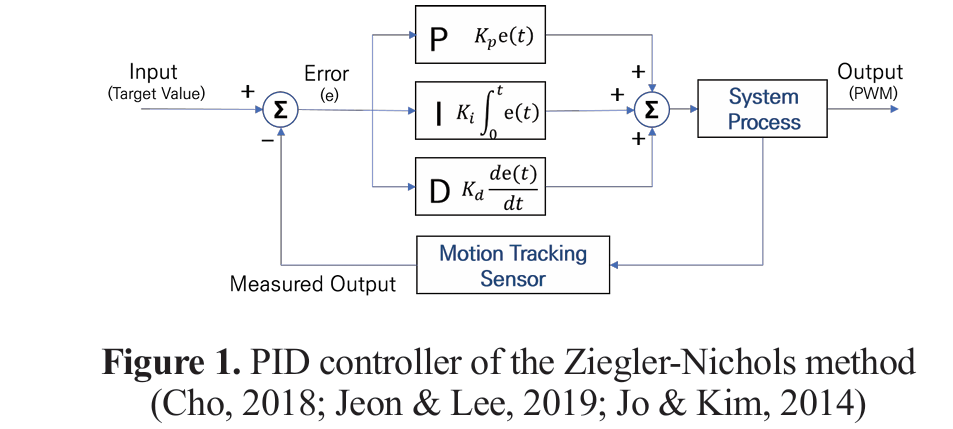 To solve this problem, studies have been published that do not cause overshoot or obtain the gain coefficient by a slightly modified proportional integral-derivative (PID) controller (Jo & Kim, 2014). However, the stabilization time could be faster for drone systems sensitive to vibration and external environmental conditions. In addition, there are cases where dual- and triple-loop PID controllers (Jung & Chung, 2016) are used via different methods. However, in practice, an empirical approach that requires reconfiguration depending on the hardware conditions and circumstances of the configured drone and derives an optimal value requires further experimentation to identify a PID controller suitable for the ultimately implemented drone (Kim, Lim & Heo, 2012; Oh et al., 2018; Tiep & Ryoo, 2017; Ullah et al., 2020). Therefore, a drone in the form of a multi-purpose ultra-small quadcopter with functions such as clustered flight, autonomous driving, target recognition for military drones, and a hovering function for stable flight performance of the manufactured micro-quadcopter drone is proposed in this paper. The experiment for determining the optimal gain factor by applying a double-loop PID (Dual-PID) controller (Jeon & Lee, 2019) was conducted empirically by comparing and analyzing the process of optimizing the gain factor and the experimental results (Cha et al., 2015; Joo et al., 2022; Kim, Park & Hwan, 2018; Yoon et al., 2017; Zubowicz, Arminski & Kusalewicz, 2019).
3. Design of Micro Drone System
3.1 Wearable Device Design for Micro Drone Control Instead of a conventional joystick, the proposed drone is commanded via a sensor glove that responds to hand signals. This wearable device recognizes motion information about the sensor value based on the user’s hand signal through a flexible sensor and a gyro sensor on a glove shaped substrate, converts this information into digital code, and transmits it as a command signal to control the drone. Figure 2 illustrates the design of a sensor glove for controlling the micro drone.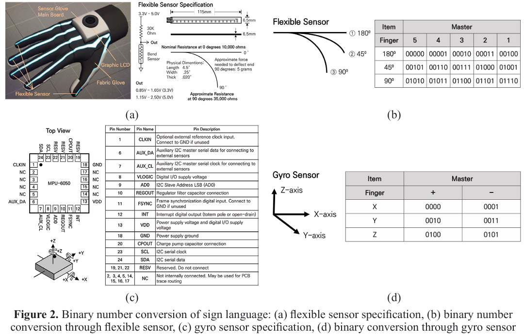 The method for recognizing the degree of flexion of the finger involved first placing the SEN-10264 f lexible sensor on all five fingers, calculating the amount of resistance change according to the degree of bending, and converting the degree of bending to a binary number. The MPU6050 sensor, a motion tracking sensor built into the master main board located on the back of the hand, recognizes information in the +/- directions of the X, Y, and Z axes and converts it to binary numbers. A 9-bit code was formed by combining the binary codes received from the two sensors. The drone was controlled by converting the combined binary number into a user-defined command for drone control.
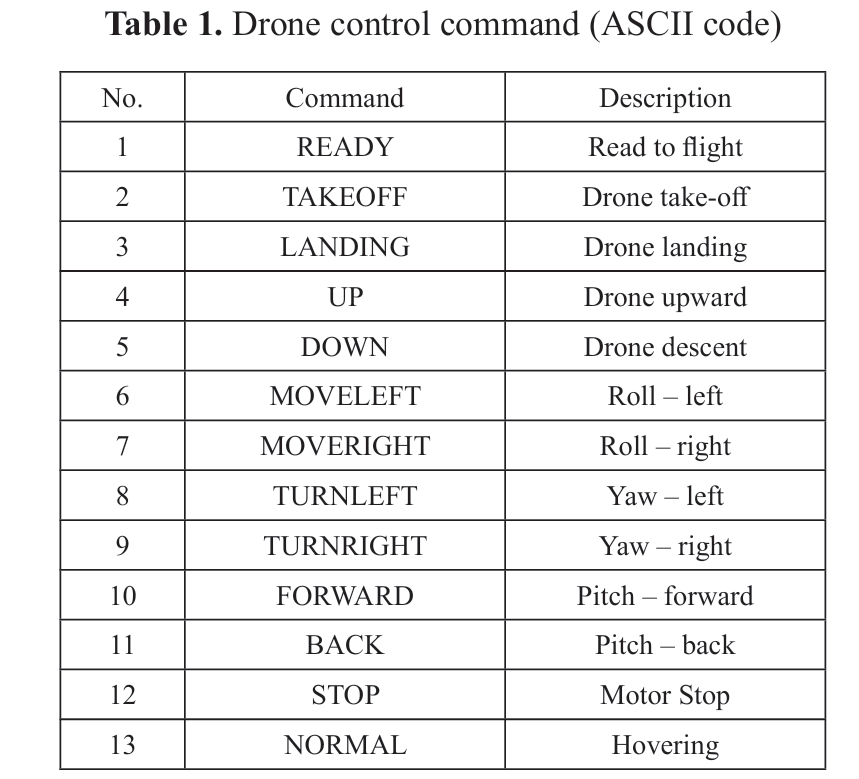
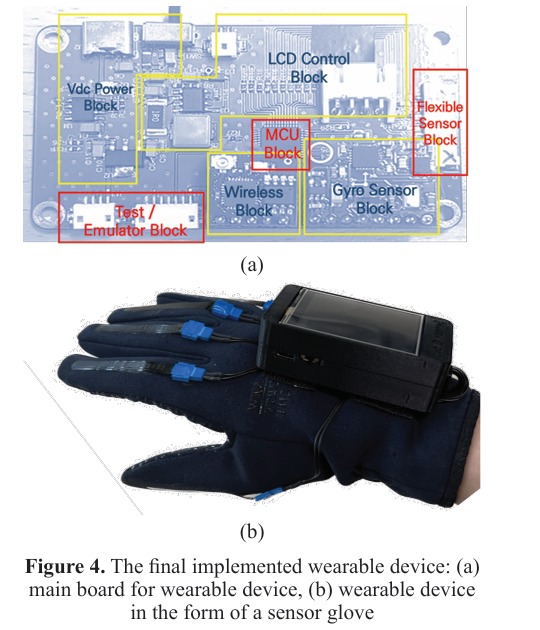
 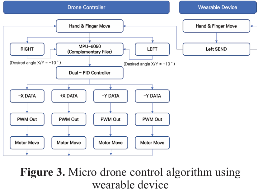 Figure 3 shows the algorithm for controlling a drone using a wearable device in the form of a sensor glove. A binary digital code was used to control the drone by combining the degree of f inger bending and the hand position information collected via the wearable device. The commands for control are summarized using the ASCII code from Table 1. A wearable device for controlling the micro drone was implemented, as shown in Figure 4. An ARM 32-bit Cortex-M3 Microcontroller was used for the microcontroller unit. Five flexible sensors were used to measure the degree of f inger bending, while a gyro sensor was used to measure hand position and movement. In addition, a 3.7 V, 1,300 mAh lithium-ion battery and a 2.4-inch graphic LCD were placed on top of the glove to display the sensor and battery status information.3.2 Hardware Design of Micro Drone In this work, a drone is designed as an ultra-small quadcopter that can be used for military purposes in the future. It is a micro drone that weighs less than 250 g and has been developed as a multi purpose drone with various functions, such as clustered flight, autonomous navigation, target recognition, and hovering. The mesh network method and GPS technology were first used to establish a two way communication environment between the wearable device which controls the drone and the drone itself, in order to implement the swarm flight function. Dual WiFi was used to solve the data traffic problem. To implement the hovering function, which serves to maintain f light posture, a gyro, an accelerator, a barometer, an optical flow, and a magnetic sensor, and one 2M CMOS camera were used to implement autonomous driving and target recognition. Real time streaming was made possible by acquiring frames at a rate greater than the FPS, and three ultrasonic sensors assisted in calculating the distance to the recognized target. Figure 5 shows a block diagram of the main board of the designed micro drone.
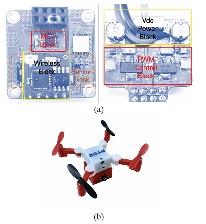
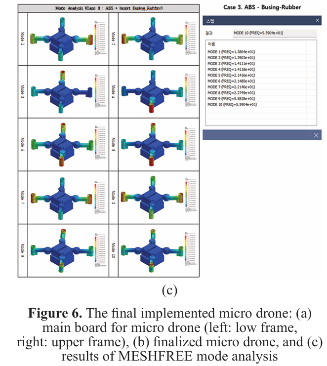
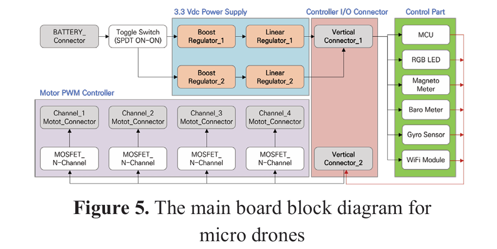 Figure 6(a) shows the micro drone main board (left: low frame, right: upper frame) and its simple configuration, and 6(b) shows the finalized micro drone. The drone used the ARM 32-bit Cortex-M3 Microcontroller. For the motion tracking sensor, an MPU6050 was used to read the drone status data through I2C communication, and the body frame of the developed drone was designed to be 50×50 mm²with the wing block folded and to have a final realized weight of 173 g. To minimize the effect of vibration transmitted to the main board of the four motors, the upper frame of the aircraft was connected to the motor, the sensor was embedded in the main board, which was separated into a lower frame with a board, and rubber bushing was used to prevent motor vibration from being transmitted directly to the main board In addition, in the case of the manufactured airframe, the weight of the drone was determined by using ABS-based PLA 1.75 material, and the resonant frequency was analyzed through MODE analysis, using the MESHFREE simulator from “MIDAS Information Technology.” As shown in Figure 6(c), the stability of the structure was confirmed at a resonance frequency of 14–56 Hz, which exceeds the natural wind resonance frequency of 10 Hz.3.3 System Protocol for Clustered Drones The command protocol defined for a clustered f light is configured to be distinguished based on the amount of information in the transmitted packet. First, in the case of the entire protocol, the ASCII code was used to use start/end bits and tokens as symbols. In the case of multiple control drones, the packet is defined in the form of a start bit ([), followed by the number of control drones, the control target drone ID, the token (,), the control command, and finally, the end bit (]). In the case of controlling a single drone, the packet is defined in the form of a start bit ([), followed by the ID of the control target drone, the token (,), the control command, and the end bit (]). At this time, in the case of the control command, the drone is controlled according to the command rule mentioned in Table 1.
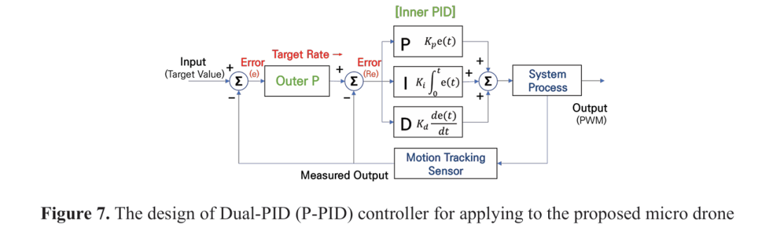
 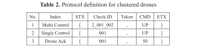 Table 2 shows the protocol definitions for clustered drones. In addition, if the wearable device for controlling the drone and the drone do not form a direct communication path (Drone Ack), the drone transmits information on its ID and battery level to check its connection status. In the case of the configured protocol, the packet is transmitted in the form of a start bit ([), followed by the control target drone ID, the token (,), the remaining battery level, and the end bit (]). 3.4 Proposed Dual-PID Controller For the PID controller used to maintain the stable f light posture of the micro drone proposed in this study, a dual-PID controller with a double loop structure improved from the existing PID controller of the Ziegler-Nichols method was used. The hovering function was implemented using a P-PID controller. In the case of the motion tracking sensor, the accuracy and stabilization speed were improved by the addition of a barometer, an optical flow, and a magnetic sensor besides the basic gyro and accelerator sensors. Figure 7 shows the structure of the designed dual-PID controller, which compensates for flight motion errors, due to motor vibration and external environmental factors, by adding an external P controller to the basic PID controller structure, as it has been shown in Figure 1. This method has the benefit of decreasing the signal convergence speed and stabilization time for the target operating value. A general PID controller is inevitably vulnerable to noise caused by external environmental factors, because it uses only the error value of the angle as a parameter for posture correction. Therefore, as shown in equation (1), the final control value of the PID controller is determined by the angular error value e. Currently, MV(t) is the final control value obtained through the PID controller, Kp is the proportional gain coefficient, Ki is the integral gain coefficient, Kd is the differential gain coefficient, and e is the angular error (Lee, 2020a; Jeon & Lee, 2019).
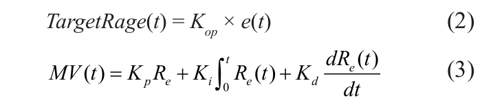
 For this reason, in this study, e – the error value of the current angle, and the external proportional gain constant are calculated to compensate for the error, due to vibration and external environmental factors, by using the P-PID controller designed as shown in equations (2) and (3). In this way, the target rate, which is the angular velocity, is configured, and the PID control value is ultimately determined by Re which is the error between the target angular velocity and the current angular velocity. Therefore, noise element compensation is double-processed to enable stable flight performance. At this point,
  represents the external proportional gain coefficient (Jeon & Lee, 2019)
4. Optimization of Gain Coefficient through the Dual-PID Controller
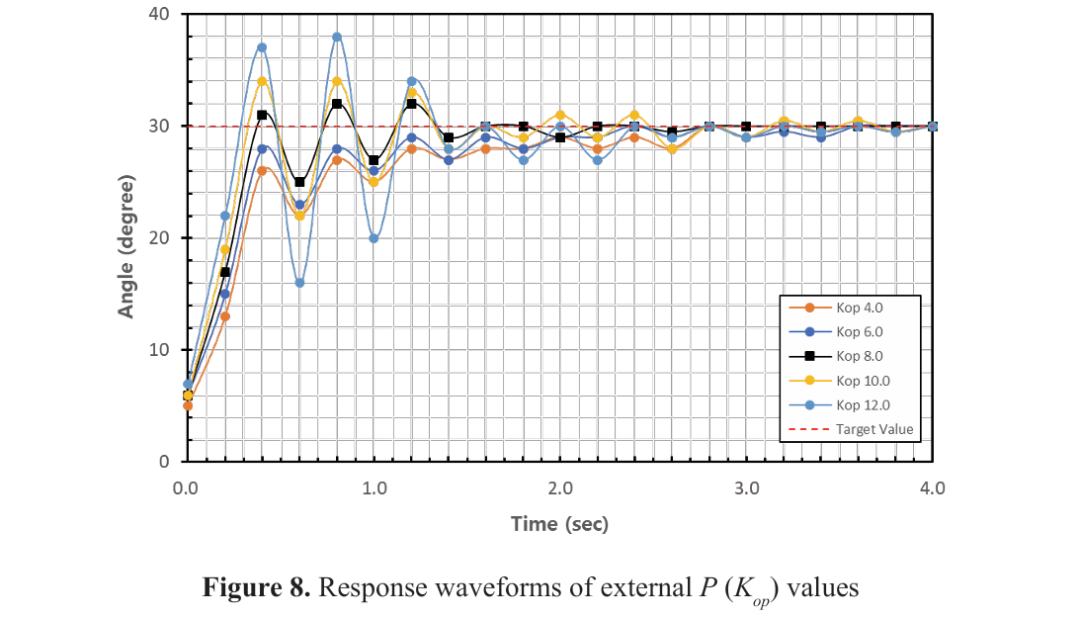
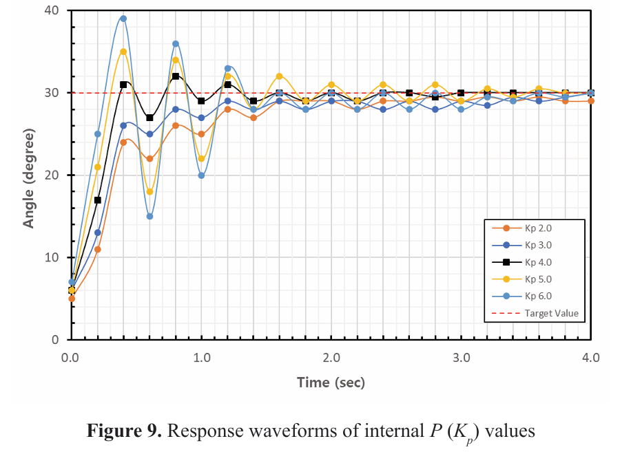
Prior to determining the optimized value for each item of the proposed P-PID controller, one axis of motion of the drone was fixed, and the target value was experimentally acquired by stabilizing a state value through an instantaneous change. When determining the optimal value for each gain constant, the external P → internal P → internal I → internal D values were derived in this order. In this study, the pitch axis was fixed, and the target angle of the roll axis was set at +30° to measure the posture correction value of the micro drone for instantaneous changes. 4.1 Optimization of External P () Value First, in the case of the external P-value () optimization step, the response waveform was measured while fixing the internal proportional, integral, and differential gain coefficients, and the external proportional gain coefficient was increased by factor of 2. Figure 8 compares the response waveforms for the time and state required to reach the normal target value, as the vales of coefficient ranged from 4 to 6, 8, 10, and 12. The smaller the external P value was, the less overshoot occurred; however, for the target angle, the convergence speed was slow, and the overshoot increased as the external P value increased. Nonetheless, it was confirmed that the target angle was quickly approached, and that the greater the external P value was, the more unstable the system became and the longer it took to attain stability. As a result of the experiment employed to determine the external P value, which is the first step, the most stable response waveform with a small overshoot and fast convergence speed was obtained when = 8. Consequently, this value was chosen as the final optimal value.4.2 Optimization of Internal P ( ) Value In step 2, the external P value () obtained in step 1 is fixed at 8. The internal integral and differential gain coefficients are also fixed, and the value is derived to represent the internal proportional gain coefficient. Figure 9 compares the response waveforms for the time and state required to reach the normal target value, as the values of coefficient ranged from 2 to 6. Regarding , the internal P value, the smaller internal P value resulted in less overshoot; but this adjustment corresponded to a decrease in convergence speed towards the target angle. However, it was confirmed that the larger the external P value, the more unstable it became and the longer it took to attain stabilization. It was found that the overall characteristics were identical to the external P value, and for fast steady-state convergence, it was confirmed that the larger the external P value, the faster the convergence. As a result of the experiment employed to determine the internal P value, which is the second step, the most stable response waveform with little overshoot and fast convergence was demonstrated when = 4.0. Therefore, this value was selected as the final optimal value. 4.3 Optimization of Internal I (
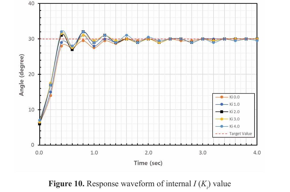
 ) Value Step 3 fixes the external P value (= 8) and internal P value (= 4.0) obtained in steps 1 and 2, and derives the internal integration gain coefficient value, while also fixing the internal differential gain coefficient. The response waveform was measured, while the value was increased by +1. Figure 10 compares the response waveforms for the time and state required to reach the normal target value, as the values change from 0 to 4. In the case of the internal I value, the overshoot increased with increasing the values, and the overall system cycle increased; however, it was confirmed that this did not have a significant effect on the proposed P-PID controller. As a result of the experiment conducted in step 3 to determine the internal I value, the most stable response waveform with a small overshoot and fast convergence speed was obtained when = 1.0. Consequently, this value was chosen as the final optimal value4.4 Optimization of Internal D (
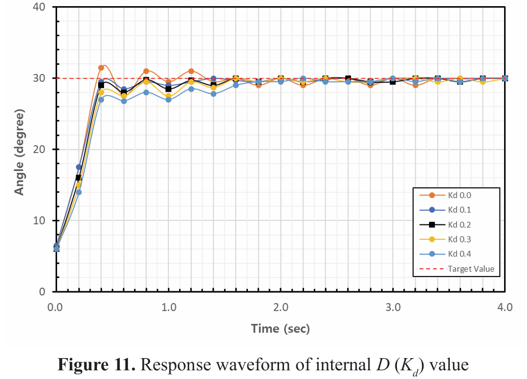
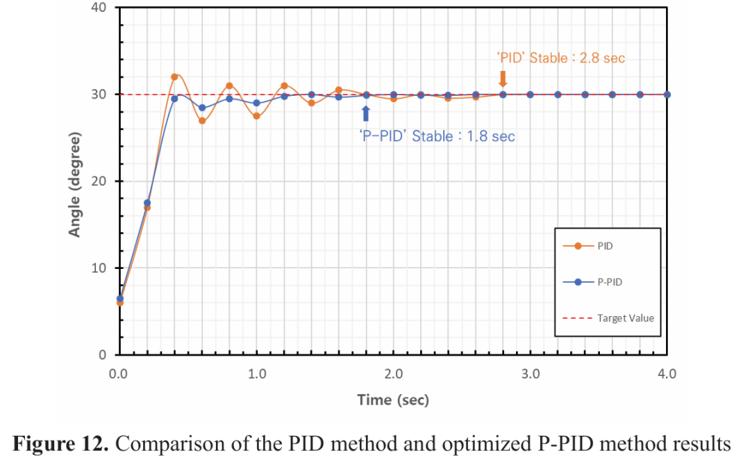
 ) Value In step 4, the external P value (= 8), internal P value (= 4.0), and internal I value (= 1.0) obtained in steps 1, 2, and 3 are fixed, and the internal differential gain coefficient value Kd is derived. The response waveform was measured, while the value was increased by 0.1. Figure11 compares the response waveforms for the time and conditions required to reach the normal target value, while the values of coefficient ranged from 0.0, 0.1, 0.2, 0.3, and 0.4. In the case of the internal D value, it was confirmed that the larger the gain, the more effective it was at suppressing the overshoot; and once the D exceeded a certain value, overshoot almost never occurred. It was also confirmed that the arrival at the target angle was rather slow. As a result of the experiment conducted in step 4 to determine the internal D value, when = 0.1, the most stable response waveform was obtained, which reached the target angle at a normal speed, while suppressing overshoot. Therefore, this value was selected as the final optimal value. 4.5 Final proposed optimized P-PID value = 8, = 4.0, = 1.0, and = 0.1 were f inally selected as the optimal values for all four steps of the P-PID controller, which is the core of the hovering function for the stable flight performance of the proposed micro drone, as determined by the experiments. To verify the stability of the selected optimization value, a comparison was made with the application of the basic PID controller of the existing Ziegler Nichols method. Figure 12 depicts the results of the comparison between the PID method and P-PID method using optimal values. As a result, the flight stabilization time was reduced from 2.8 seconds to 1.2 seconds, demonstrating that it functions well even in the presence of external factors such as vibrations caused by the motor. Therefore, it was demonstrated that it functions well even in the presence of external environmental factors such as vibration caused by the motors and by wind.
5. Conclusion
In this study, a quadcopter-type micro drone with military applications and a wearable sensor glove for controlling it were developed. The present paper introduced an improved P-PID controller derived from the Ziegler Nichols method, demonstrating its effectiveness through experiments. The wearable device utilized a microcontroller, five flexible sensors for finger bending, a gyro sensor for hand motion, and a 2.4-inch graphic LCD powered by a 3.7 V battery to control the drone. The micro drone has a weight less than 174g and boasts capabilities such as swarming flight,driving autonomously, recognizing targets, and maintaining a fixed posture. The experiment employed a mesh network and GPS technology for swarming flight, dual WiFi for data management, and various sensors, including a 2M CMOS camera and ultrasonic sensor, for autonomous driving and target recognition. The core of the drone was the microcontroller, and for motion tracking, the MPU6050 sensor was used through I2C communication. The stable flight for the micro drone was achieved by using an optimal P-PID controller. In the experiments, the pitch axis was fixed and the roll axis target angle was set to +30°, in order to measure the attitude correction value of the drone. The optimal P-PID gain coefficients, = 8, = 4.0, = 1.0, and = 0.1, were derived and compared with those of the Ziegler Nichols PID controller. The new controller reduced flight stabilization time from 2.8 seconds to 1.8 seconds, showing robust performance in the presence of external factors such as motor induced vibrations and windREFERENCES
Cha, G. H., Sim, I., Hong, S. G., Jung, J. H. & Kim, J. Y. (2015) A Study of Method and Algorithm for Stable Flight of Drone. Journal of Satellite, Information and Communications. 10(3), 32-37. Cho, Y. (2018) A triple nested PID Controller based on sensor fusion for quadrotor attitude stabilization. The Transactions of the Korean Institute of Electrical Engineers. 67(7), 871-877. doi: 10.5370/ KIEE.2018.67.7.871. Jeon, D.-S. & Lee, S. (2019) Double-Loop PID Controller for Quadcopter Attitude Stabilization. The Journal of Korean Institute of Communications and Information Sciences. 44(04), 748-754. doi: 10.7840/ kics.2019.44.4.748. Jo, Y. & Kim, H.-S. (2014) Posture Stabilization Control of QuadCopter Using Sensor Fusion and Modified PID Control. Journal of Institute of Korean Electrical and Electronics Engineers. 18(3), 376–382. doi: 10.7471/IKEEE.2014.18.3.376.Joo, M., Yoon, J., Junejo, A. R. & Doh, J. (2022) Optimization: Drone-Operated Metal Detection Based on Machine Learning and PID Controller.International Journal of Precision Engineering and Manufacturing. 23(5), 503-515. doi: 10.1007/ s12541-022-00639-w.Jung, W.-H. & Chung, J.-P. (2016) Implementation of Quad-rotor Hovering Systems with Tracking. Journal of Advanced Navigation Technology. 20(6), 574–579. doi: 10.12673/JANT.2016.20.6.574. Kim, H.-S., Park, B.-H. & Han, Y.-H. (2018) Hovering System for Autonomous Flight of Multi-copter. The Journal of Korean Institute of Information Technology. 16(12), 49-56. doi: 10.14801/jkiit. 2018.16.12.49. Kim, J. S., Lim, Y. D. & Heo, J. Y. (2012) The Simulator for Control of Quadcopter using Sensor Combination. Journal of Korean Institute of Information Technology. 10(7), 1-11.Lee, S. (2020a) The modified Ziegler-Nichols method for obtaining the optimum PID gain coefficients under quadcopter flight system. Journal of the Korea Convergence Society. 11(11), 195-201. doi: 10.15207/jkcs.2020.11.11.195Lee, Y. U. (2020b) A Study on the Effective Military Use of Drones. Journal of Information and Security. 20(4), 61-70. doi: 10.33778/ kcsa.2020.20.4.061.Oh, J.-W., Seol, J.-W., Gong, Y.-H., Han, S.-J. & Lee, S.-D. (2018) Drone Hovering using PID Control. The Journal of the Korea Institute of Electronic Communication Sciences. 13(6), 1269–1274. doi: 10.13067/JKIECS.2018.13.6.1269. Tiep, D. K. & Ryoo, Y.-J. (2017) An Autonomous Control of Fuzzy-PD Controller for Quadcopter. International Journal of Fuzzy Logic and Intelligent Systems. 17(2), 107-113. doi: 10.5391/ijfis.2017.17.2.107. Ullah, S., Mehmood, A., Khan, Q., Rehman, S. & Iqbal, J. (2020) Robust Integral Sliding Mode Control Design for Stability Enhancement of Under-actuated Quadcopter. International Journal of Control, Automation and Systems. 18(7), 1671-1678. doi: 10.1007/s12555-019-0302-3. Yoon, D.-B., Lee, K.-Y., Han, S.-G., Kim, Y.-H. & Lee, S.-D. (2017) A Study on Flight Stabilization of Drones by Gyro Sensor and PID Control. The Journal of the Korea Institute of Electronic Communication Sciences. 12(4), 591–598. doi: 10. 13067/ JKIECS.2017.12.4.591. Yun, S. Y. & Park, S. J. (2018) A Study of Foreign Military UAV Development Trend and Operational Cases for the UAV Developments of Republic of Korea Armed Forces. Strategic Studies. 25(1), 205-232. Ziegler, J. G. & Nichols, N. B. (1993) Optimum Settings for Automatic Controllers. Journal of Dynamic Systems, Measurement, and Control. 115(28), 220-222. doi: 10.1115/ 1.2899060. Zubowicz, T., Arminski, K. & Kusalewicz, A. (2019) Quadrotor Flight Controller Design Using Classical Tools. International Journal of Control, Automation and Systems. 18(3), 730-738. doi: 10.1007/s12555 018-0710-9author
From 
著作权归作者所有,欢迎分享,未经许可,不得转载
首次发布时间:2025-07-05
最近编辑:1年前