NFX|齿轮泵(Gear Pumps)分析
FEM Strength Analysis of Circumferential Compensation with Integrated Lips in Gear PumpsFaculty of Mechanical Engineering, Wrocław University of Science and Technology, Łukasiewicza 5, 50-371 Wrocław, Poland; piotr.osinski@pwr.edu.pl* Correspondence: urszula.warzynska@pwr.edu.plAbstract: Currently, gear pumps are developed with a aim to increase their efficiency, reduce internal leaks, and increase their working pressures. This development direction requires new solutions which would compensate backlash while ensuring an optimal size of the gaps for the entire range of working pressures. One of the solutions intended to meet this demand is to design circumferential compensation with the so-called integrated lips. The presented backlash compensation method is the result of research performed as part of a project named designing High-Pressure Gear Pumps.The project was granted funding under path A of the Applied Research Program, contract No. PBS3/A6/22/2015. The research works were performed in the Laboratory of Hydraulic Drives and Vibroacoustics of Machines at Wrocław University of Science and Technology, and in cooperation with Hydrotor SA.Keywords: strength analysis; finite element method; circumferential compensation; gear pumpInternal leaks in a gear pump depend on particular dimensional tolerances applied in the manufacturing process. The tolerances translate directly into backlash occurring between the gears (the displacement elements) and the individual pump components which limit the displacement chamber [1–4]. In an external gear pump, two types of backlash are identified: radial backlash and axial backlash [3,5]. The first type of backlash is also referred to in the literature as circumferential backlash [6]. The circumferential gap is formed by two surfaces: the surface of the machine-turned casing, and the surface of a cylinder defined by a circle whose radius is limited by the tip of the tooth addendum in the displacement element. A gap designed with such limitations does not have a constant value along the entire circumference, as the gears move within the limits of the bearing slackness towards the suction space. As a result, in conventional pumps, which are not provided with radial backlash compensation, the circumferential gap is crescent shaped. The crescent thickness increases towards the pressure chamber (Figure 1b). In such designs, the size of the gap varies within a range from 0.01 to 0.3 mm. In this case, the circumferential backlash is a type of gap with one fixed wall and one moveable wall which rotates in the direction opposite to the direction of the pressure drop. Such a solution is advantageous, as the rotation of the gear causes the liquid to rise from the suction space to the discharge space, while limiting leaks due to pressure differences at the ends of the gap [7].The axial backlash is ring shaped and is limited by the diameter of the circle defined by the teeth roots and the shaft on which the gear is cut or mounted. Some limited leaks are appreciated and used in the cooling and lubricating of the bearings. After it passes through the bearings, the working liquid is directed to the suction chamber with the use of dedicated grooves. Therefore, internal tightness cannot be ensured at a 100% level. Without lubrication and heat removal, the pump would seize [8,9]. In addition, some part of the volumetric loss passes through the axial gap directly to the suction space, where it provideslubrication and cooling to the surfaces of the slide bearing blocks in contact with the gears.The values of the axial backlash are smaller by approximately one order than the values of the circumferential backlash. In typical pumps, these values are within a range from 0.01 to 0.05 mm [3,4]. The recommended backlash value also depends on the size of the pump.Smaller backlash values are assumed to be more appropriate for units with lower specific deliveries [7].
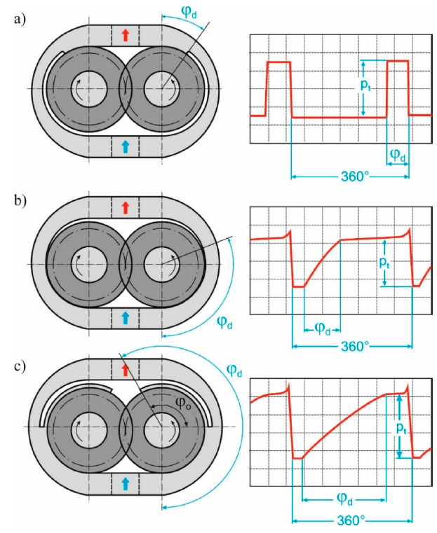
Figure1. Schematic diagram of circumferential gear sealing together with the changes in the circumferential pressure measured in the tooth space as a function of the rotation angle of the gear: (a) pump with radial backlash compensation, (b) pump with gears shifted from the hydrostatic pressure of the liquid, (c) pump with circumferential backlash compensation. Indications: —wrapping angle
 —caulk angle
 —discharge (output) pressure [10]Solutions based on backlash compensation allow better running-in of the engaged elements and preserve a constant value of the gap size despite the frictional wear of the parts. In the current commercial pumps, the main focus is on compensating axial backlash, but if increased internal tightness is required, circumferential backlash must be additionally compensated as well. The circumferential gap is compensated with the use of two methods [7]. The first method consists in a local compensation of the backlash along a short segment. For the purpose of this article, the first method is thus further referred to as radial backlash compensation (Figure 1a). The second method consists in ensuring a constant size of the gap along the entire circumference (Figure 1c). This method is thus referred to here as circumferential backlash compensation (Figure 1c). Designs with circumferential backlash compensation have:*A constant value of the gap size along the entire circumference, regardless of the temperature and the operating pressure*A linear pressure increase along the circumference of the gears in contact with the pump casing, i.e., from the suction channel to the pressure channel;*A lubricant film of required thickness maintained on the entire circumferential surface of the gearsThe above compensation methods can be applied in different forms: mechanical,hydraulic, or mixed-hydromechanical [7]. Due to the presence of significant forces, the hydraulic method seems to be an optimal solution. Currently, the mechanical compensation is used to complement the hydraulic compensation. Mixed compensation is particularly useful during the start-up phase, when the pressure does not yet provide the minimum pressing force to maintain appropriate internal tightness of the pump. The influence of the applied compensation method on the total efficiency of the pump is presented in Figure 2. A comprehensive set of characteristics was prepared on the basis of information collected from technical specifications provided by manufacturers of gear pumps (Bosch, Casappa, Marzocchi, Hamworthy, Hidroirma, Orsta, Parker, PZL-Hydral,Rexroth, WPH, and VPS) and on the basis of own research on experimental designs of pumps with circumferential backlash compensation [7,10].
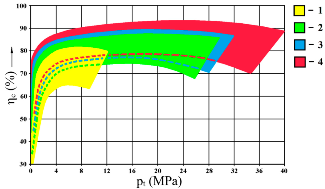
Figure 2. Total efficiencies ηc of gear pumps as a function of discharge pressure Pt and backlash compensation (based on technical data provided by major manufacturers and on own research): 1—no compensation, 2—with axial compensation, 3—with axial and radial compensation, 4—with axial and circumferential compensation [10].The graph indicates that the use of different backlash compensation methods significantly increases efficiency and working pressures in gear pumps. In currently produced pumps (provided with axial or with axial and radial backlash compensation), nominal discharge pressures reach values up to 28 MPa, and instantaneous maximum pressures (in a pulse) up to 32 MPa. The use of the new circumferential backlash compensation method allows an increase in the pressure by more than 20%, to the level of 36 MPa (for nominal loads) and of 40 MPa for short maximum loads. Additionally, the increase in internal tightness causes an increase in volumetric efficiency on average by 5% [10].
2.Research Scope and PurposeThe purpose of this research was to identify the effort on the casings of gear pumps with circumferential backlash compensation and to measure the effort parameters and the maximum displacement of the compensation lip. The analysis was performed for different gear rotation angles and with the assumed loads corresponding to the highest discharge pressure of 40 MPa. The need for a more detailed analysis of the lip strength resulted from earlier experiences on the test stand, which demonstrated that this strength is an element decisive for the possibility to use lip compensation. Figure 3 shows the first prototype of circumferential compensation with a separated lip after durability tests [11].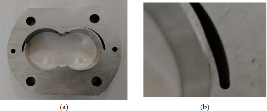
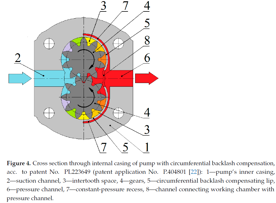
Figure 3. Inner casing in first version of circumferential compensation: (a) after durability tests, (b) view of narrowing in compensating lip cross section [11]. In the subsequent step, finite element method (FEM) analyses allowed adjustments to the thickness of the compensation lip to ensure an adequate strength and circumferential backlash compensation in the gear pump prior to preparing the prototype of the pump casing. FEM is a tool frequently used in research works at the stage of designing new elements. The literature mentions interesting recent research into new pump designs following helicoidal [12–14] and involute [15,16] shape, into hydraulic motors [17–19], as well as into thermal processes in hydraulic pumps and motors [20,21]. This research on numerical calculations is a development of previous analytical strength calculations presented in the following publications [7,11].The numerical analysis focused on designs of pump casings having circumferential backlash compensation and gears with straight teeth. A solution comprising integratedlip compensation is protected under patent documents No. P.404801 (PL223649 [22]) and P.418261 (PL230845 [23]). Figure 4 shows the concept of the solution protected under patentPL223649 (application No. P.404801 [22]). The patent additionally discloses a possibility to alternatively make the compensation lip in the form of a separate element. The circumferential backlash compensating lip 5 is made symmetrically in the native material of the casing and across the entire width of gears 4. This solution entailed the need to make an additional channel 8 arranged symmetrically in the elastic lip and axially with respectto the pressure channel. Channel 8 allows the work medium to be pumped from intertooth space 3 to pressure channel 6. The discharge pressure acts on the outer surface of the circumferential backlash compensating lip 5 through recesses 7. The circumferential backlash compensating lip 5 is pressed simultaneously against both of the engaged gears 4. Figure 5 is a photograph of a detail with circumferential backlash compensation according to patent PL223649 (application P.404801 [22]). This design employs integrated lips with thickness increasing towards the restraint. Additionally, a properly shaped lip in the area of the pressure channel (the “dovetail” shape) ensures that the compensation lip can be displaced only to a defined limit. The displacement limiter was patented in PL234070 (application P.427264 [24])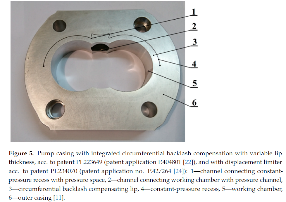
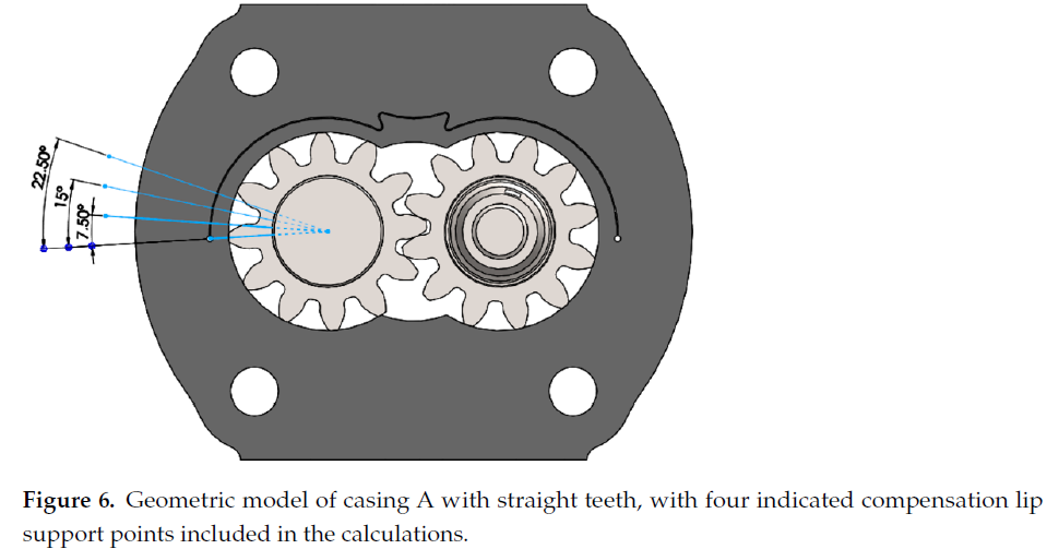
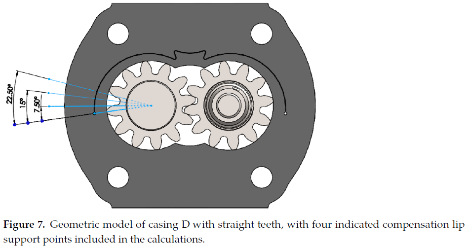
Of a series of casings analyzed in the previous research, here the analysis was performed for two types of casings having the minimum and the maximum compensation lip thickness. The casings have different compensation lip geometry and lip wrapping angle:Type A: lip wrapping angle 90°, external lip radius 28.9 mmType D: lip wrapping angle 95°, external lip radius 30.7 mmEach of the analyses included four meshing points which have an influence on how the circumferential backlash compensation lip is supported by the tips of the gears. The first point was defined so that the tip of the driven gear supported the compensation lip in its starting point, while the remaining three points were defined as a result of rotating the gears by an angle of 7.5°, 15°, and 22.5° with respect to its original position. Figures 6 and 7 show the analyzed geometric models with the indicated four variants of the compensation lip support in each of the geometries. The numerical calculations of the pump casings were based on the material properties of the PA9 aluminum alloy. This alloy has good strength parameters as well as high tensile and fatigue strength. The gears were based on the material properties of the 16HG alloyed case-hardening steel. The mechanical and physical properties of the two materials are presented in Table1
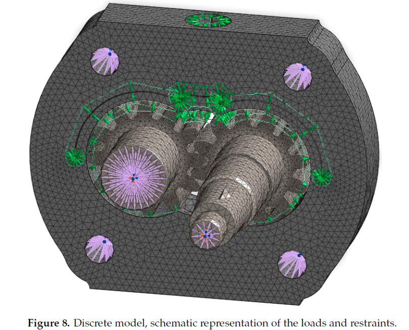
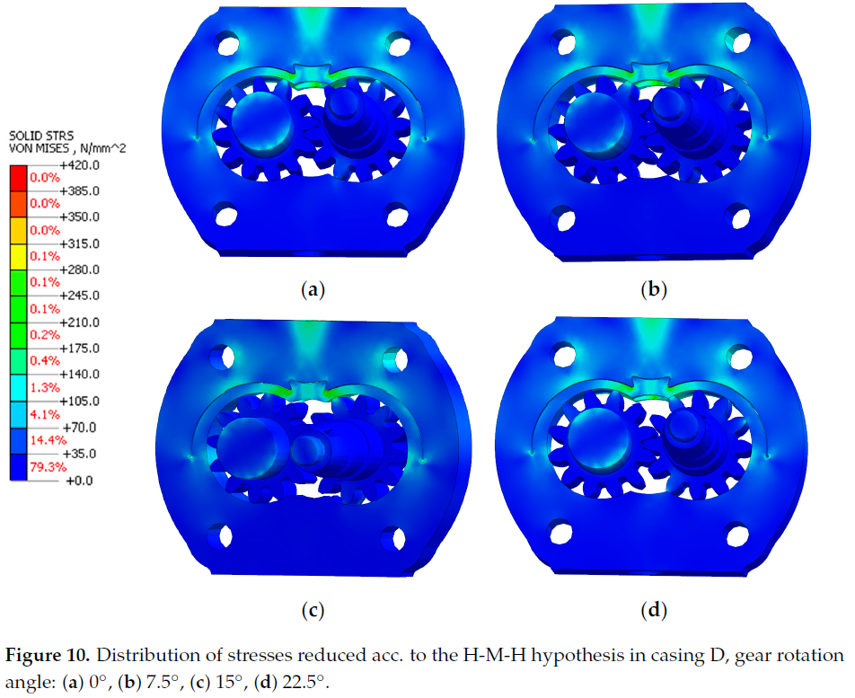
4. Discrete Models and Boundary ConditionsThe discrete models of the analyzed casings were constructed by dividing the geometric models with finite tetrahedral elements. The size of the discrete elements was selected to enable a possibly accurate correspondence with the shape of the model, particularly in narrow gaps at the compensation lips, albeit without excessively increasing the calculation time.The calculation models accounted for the load due to working liquid pressure. Each investigated pump casing was loaded with a gradient of pressure increasing linearly from the suction channel towards the pressure channel within a range from 0 MPa to the discharge pressure value of 40 MPa. A discharge pressure of 40 MPa was applied in the gap between the circumferential backlash compensation lip and the casing and in the pressure channel. The casing was loaded symmetrically on the sides of both the active and the passive gears. The model was restrained in four bolt holes fitted in the casing. Friction contact was applied in the locations where the gears contact the casing and mesh with each other. Figure 8 schematically shows the loading of the model.5. Results and DiscussionStatic linear FEM calculations of strength were performed in the Midas NFX software. The analysis results are shown as a contour line map. Figures 9 and 10 show the distribution of stresses reduced acc. to the Huber–Mises–Hencky (H-M-H) hypothesis. The results are scaled to the value of the yield point for the PA9 alloy, i.e., to 420 MPaThe greatest stress values in the pump casings are observed in the area of the compensation lip and for the PA9 alloy, and they are significantly lower than the yield point in each of the analyzed calculation cases. The maximum stress in the gears is observedon the surfaces where the teeth contact the casing and in the meshing points. The stress values in the gears are significantly lower than the yield point for steel 16HG, i.e., 590 MPa. The stresses in the gears are solely due to the compensation lip subjected to the discharge pressure. calculations of the gears did not allow for the hydrostatic thrust or the inter-tooth forces acting on the gears. The purpose of the calculations was to effort(strength) of the integrated lip compensating circumferential backlash, and therefore the stress values obtained for the gears should be viewed as approximate with respect to the actual values.Additionally, the highest stress values in the analyzed designs occurred in the compensation lip, in the region of the opening which communicates the work chamber with the pressure channel. The high value of stress in this area results from a significant narrowing in the cross-section of the integrated lip through the opening which communicates the displacement chamber with the pressure channel. The analysis of the maximum stresses in the area of the integrated compensation lip was performed by defining two measurement points, which served to read the values of maximum stresses reduced acc. to the H-M-H hypothesis. The first point was located in the vicinity of the discharge opening, and the second point was located in the vicinity of the lip restraint (Figure 11).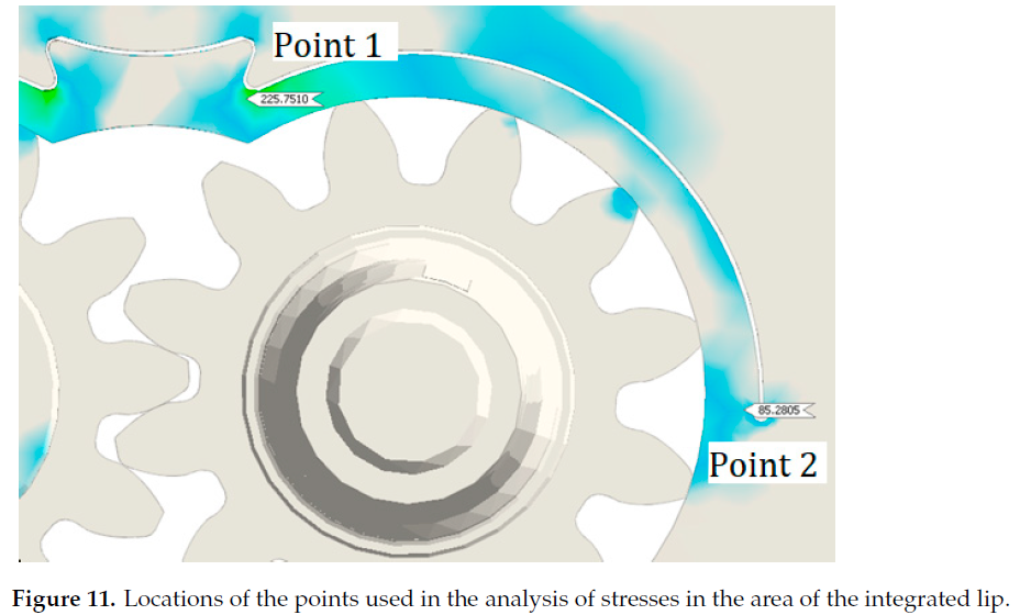
The maximum numerically calculated stresses in the integrated compensation lip,in the area of the pressure channel (point 1), are within the range from 196.10 MPa to 271.71 MPa and are smaller by 53.31% and 35.31%, respectively, than the yield point for the PA9 alloy (R0.2 = 420 MPa). On the other hand, the maximum stresses in the starting point of the lip, on the side of the active gear (point 2), are within the range from 64.41 MPa to 85.28 MPa and are smaller by 84.66% and 79.7%, respectively, than the yield point for alloy PA9. Figure 12 shows detailed comparison of stress values read in points 1 and 2 for all the analyzed angular positions of the gears.
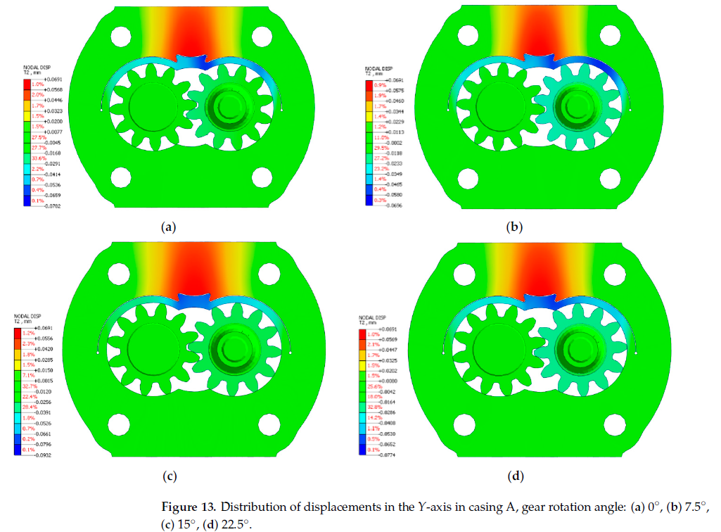
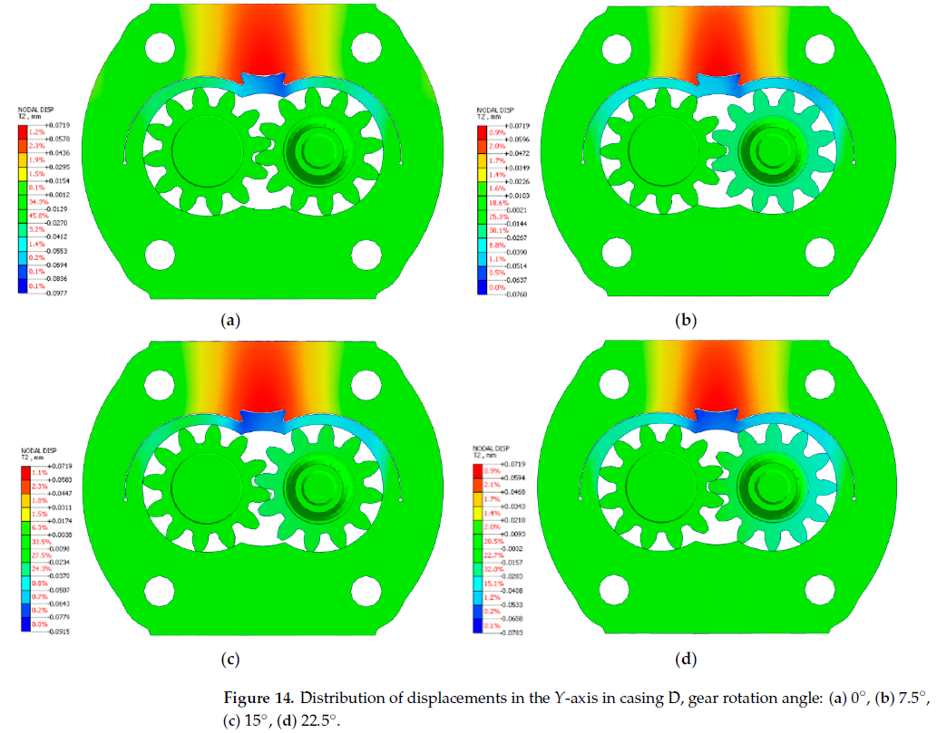
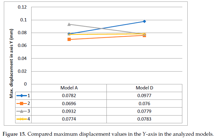
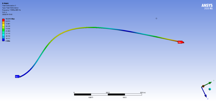
Figures 13 and 14 show the distribution of displacement in the Y-axis in the analyzed designs. The analysis of such a displacement distribution in the Y-axis is important for the reduction in circumferential backlash in a gear pump casing. In the investigated calculation cases, the circumferential backlash compensation is better for higher values of displacements in the Y-axis. In such case, the compensation lip presses against the gears on the pressure side with greater force.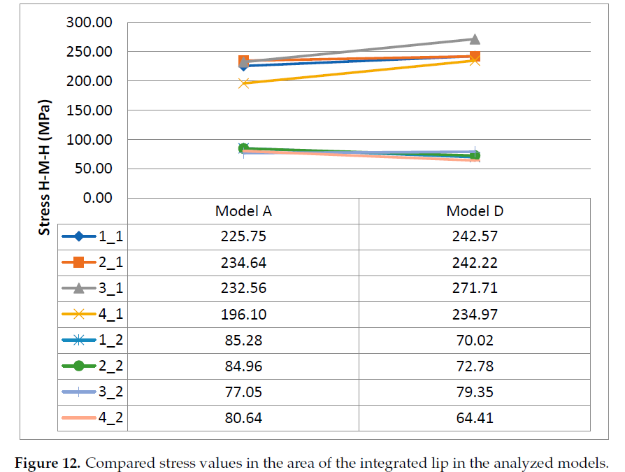
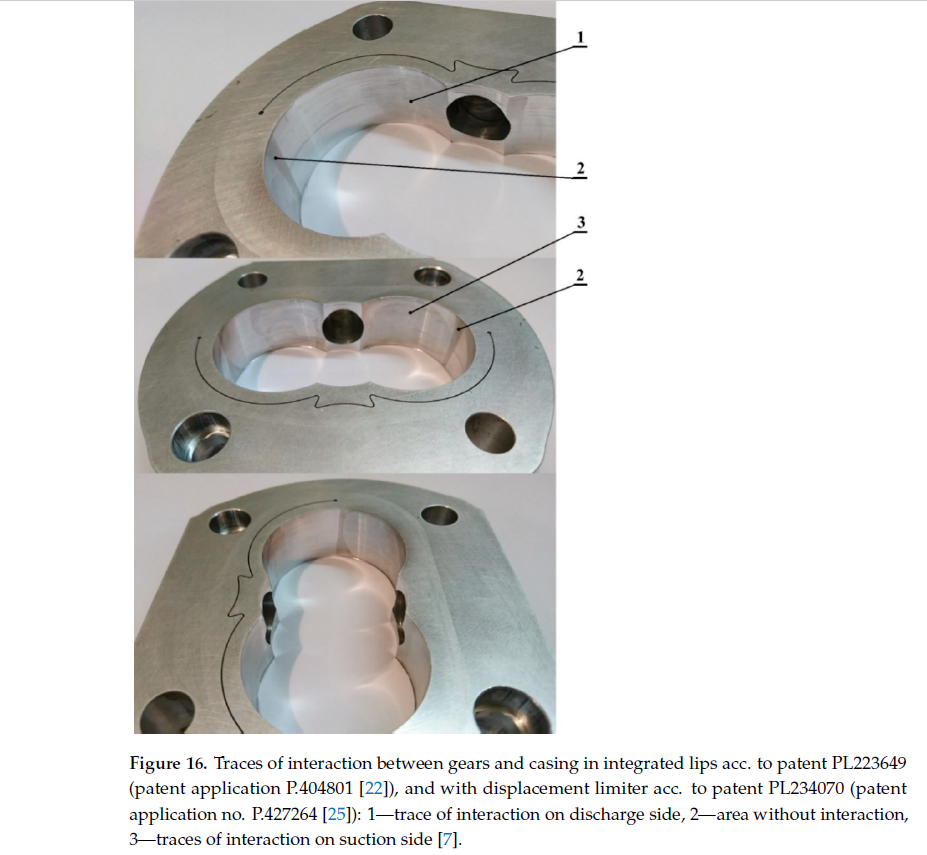
The maximum displacement values of the compensation lip in the investigated models of casings A and D were compared in the form of graphs shown in Figure 15. The analysis of the displacements in the two designs allows a conclusion that casing D provides better circumferential backlash compensation, as in the majority of the calculation cases which involve the gear tips supporting the lip in four points, the displacements in the Y-axis are observed to be greater than in the case of casing A.The displacement of the lip towards the gears (axis Y) was also observed in the experimental pump. Figure 16 shows wear of the casing both on the suction side 3 and on the discharge side 1 in the integrated lip type A. Traces of the interaction are more visible on the suction side, as the gears are pushed more towards the low-pressure side.The measured thickness of the layer selected during the running-in of the pump was not greater than 0.1mm, and this fact confirms that both the investigated discrete model and the applied boundary conditions (loads and restraints) are proper. During visual inspection,the wells also revealed a limited-area matt surface 2 which indicates that the gears did not interact in this region.The tests confirmed that a need exists for further research aimed at developing a design with a pre-tensioned circumferential compensation element. Such a solution would have a greater flexibility at lower working pressure values and would also allow high internal tightness during start-up. An example of such a solution is disclosed in patent PL233989 (application No. P.427263 [25]). As the area without interaction (see number 2 inFigure 16) is limited, the wrapping angle may need to be slightly increased. Increasing the wrapping angle should allow for high strength-related and durability-related criteria for the circumferential backlash compensation lip. Additionally, in further numerical models the numerical analysis of the internal tightness of the gear pump with circumferential backlash compensation should involve its running-in. In further research, also the accumulation of solid particles in the gaps of the compensating lip influence on the operation of compensation will be analyzed, as well as further tests on the service life of the pump series.1. Osi´ nski, P.; Cie´slicki, R. External Gear Pump (in Polish), Patent. Poland, No. 230845.Patent Application No. P 418261, 10.08.2016. Pub. 31.12.2018/Applicant Name:Wrocław University of Science and Technology, Wrocław, PL; HYDROTOR PLC,Tuchola, PL 2018.2. Osi´ nski, P.; Bury, P.; Cie´slicki, R. External Gear Pump (in Polish), Patent. Poland, No.233989. Patent Application No. P P.427263,01.10.2018/Applicant Name: Wrocław University of Science and Technology, Wrocław, PL.3. Osi´ nski, P.; Cie´slicki, R.; Bury, P. External Gear Pump (in Polish), Patent. Poland, No. 234070. Patent Application No. P P.427264, 01.10.2018/Applicant Name: Wrocław University of Science and Technology, Wrocław, PL. Author Contributions: Conceptualization, P.O.; methodology, P.O. and U.W.; software, U.W.; validation,P.O.; formal analysis, P.O. and U.W.; investigation, P.O. and U.W.; resources, P.O. and U.W.; data curation, P.O. and U.W.; writing—original draft preparation, P.O. and U.W.; writing—review and editing, P.O. and U.W.; visualization, P.O. and U.W.; supervision, P.O.; project administration, P.O.;funding acquisition, P.O. All authors have read and agreed to the published version of the manuscript.Funding: This research was funded by NCBiR (Poland), grant number PBS3/A6/22/2015.Institutional Review Board Statement: Not applicable.Informed Consent Statement: Not applicable.Data Availability Statement: Not applicable.Conflicts of Interest: The authors declare no conflict of interest. The funders had no role in the design of the study; in the collection, analyses, or interpretation of data; in the writing of the manuscript, or in the decision to publish the results.1. Kollek,W. Optimizing the Efficiency of Gear Pumps and Motors. Konstruktion 1983, 4, 147–151. (In German)2. Kollek,W. Optimization of the Volume of the Gear Pumping Unit. SINH 1981, 6, 10–23. (In Polish)3. Kollek,W. Gear Pumps—Design and Exploitation; Ossolineum: Wrocław, Poland, 1996. (In Polish)4. Stryczek, S. Hydrostatic Drive; WNT:Warszawa, Poland, 1995. (In Polish)5. Judin, E.M. Gear Pumps; PWT:Warszawa, Poland, 1958. (In Polish)6. Kollek, W.; Osi´ nski, P. Modeling and Design of Gear Pumps; Wrocław University of Science and Technology Publishing House:Wrocław, Poland, 2007.7. Osi´ nski, P. High-Performance Gear Pumps;Wrocław University of Science and Technology Publishing House: Wrocław, Poland,2019. (In Polish)8. ´Sliwi ´ nski, P. The Influence ofWater and Mineral Oil on Mechanical Losses in the Displacement Pump for Offshore and MarineApplications. Pol. Marit. Res. 2018, 25, 178–188. [CrossRef]9. ´Sliwi ´ nski, P. The Influence of Water and Mineral Oil on Mechanical Losses in a Hydraulic Motor for Offshore and MarineApplications. Pol. Marit. Res. 2020, 27, 125–135. [CrossRef]10. Osi ´ nski, P. High-Pressure and Low-Pulsation External Gear Pumps;Wrocław University of Science and Technology Publishing House:Wrocław, Poland, 2013. (In Polish)11. Osi´ nski, P. Strength Calculation Methodology for Circumferential Backlash Compensation with Integrated Lips. In Advances inHydraulic and Pneumatic Drives and Control 2020; Stryczek, J.,Warzy ´ nska, U., Eds.; Springer: Berlin/Heidelberg, Germany, 2020.12. Zhao, X.; Vacca, A. Multi-Domain Simulation and Dynamic Analysis of the 3D Loading and Micromotion of Continuous-ContactHelical Gear Pumps. Mech. Syst. Signal Processing 2022, 163, 108116. [CrossRef]13. Zhao, X.; Vacca, A. Analysis of Continuous-Contact Helical Gear Pumps through Numerical Modeling and ExperimentalValidation. Mech. Syst. Signal Processing 2018, 109, 352–378. [CrossRef]14. Rituraj, R.; Vacca, A. Investigation of Flow through Curved Constrictions for Leakage Flow Modelling in Hydraulic Gear Pumps.Mech. Syst. Signal Processing 2021, 153, 107503. [CrossRef]15. Rituraj, F.; Vacca, A. External Gear Pumps Operating with Non-Newtonian Fluids: Modelling and Experimental Validation. Mech.Syst. Signal Processing 2018, 106, 284–302. [CrossRef]16. Castilla, R.; Gamez-Montero, P.J.; del Campo, D.; Raush, G.; Garcia-Vilchez, M.; Codina, E. Three-Dimensional NumericalSimulation of an External Gear Pump With Decompression Slot and Meshing Contact Point. J. Fluids Eng. 2015, 137, 041105.17. Patrosz, P. Influence of Properties of Hydraulic Fluid on Pressure Peaks in Axial Piston Pumps’ Chambers. Energies 2021, 14, 3764.18. ´Sliwi ´ nski, P.; Patrosz, P. Methods of Determining Pressure Drop in Internal Channels of a Hydraulic Motor. Energies 2021, 14, 5669.19. ´Sliwi ´ nski, P.; Patrosz, P. The Influence of Water and Mineral Oil on Pressure Losses in Hydraulic Motor. In Advances in Hydraulicand Pneumatic Drives and Control 2020; Stryczek, J.,Warzy ´ nska, U., Eds.; Springer: Berlin/Heidelberg, Germany, 2020.20. Jasi ´ nski, R. Analysis of the Heating Process of Hydraulic Motors during Start-Up in Thermal Shock Conditions. Energies 2022,21. Jasi ´ nski, R. Volumetric and Torque Efficiency of Pumps during Start-up in Low Ambient Temperatures. In Advances in Hydraulicand Pneumatic Drives and Control 2020; Stryczek, J.,Warzy ´ nska, U., Eds.; Springer: Berlin/Heidelberg, Germany, 2020.22. Osi´ nski, P. Gear Pump. Patent Poland No. 223,649, 31 October 2016. (In Polish)23. Osi´ nski, P.; Cie´slicki, R. External Gear Pump. Patent Poland No. 230,845, 31 December 2018. (In Polish)24. Osi´ nski, P.; Cie´slicki, R.; Bury, P. External Gear Pump. Patent Poland No. 234,070, 1 October 2018. (In Polish)25. Osi´ nski, P.; Bury, P.; Cie´slicki, R. External Gear Pump. Patent Poland No. 233,989, 1 October 2018. (In Polish)