DEFORM-3D_使用手册【英文版】(文字)

摘要:
本文为 DEFORM-3D V6.0 英文版完整用户手册,全面介绍该金属成形有限元仿真软件的架构、功能与全流程操作。内容涵盖前处理、求解运算、后处理三大核心模块,详述几何导入、网格划分、材料属性、边界条件、运动设置、接触关系等配置方法,讲解多种求解器、重划分规则及并行运算、批量任务运行方式。同时介绍应力、应变、温度等结果查看、数据提取功能,附带金属成形基础理论与 FORTRAN 自定义子程序开发说明,梳理仿真常见报错及排查方案。手册体系完整、内容详实,是掌握 DEFORM-3D 仿真建模、问题调试与二次开发的权威参考资料。
Preface to this manual
This manual describes the features and capabilities of the DEFORM-3D system. It also contains a description of the inputs and actions required to setup problems and run simulations. If you have not used DEFORM before we would recommend that you go through the lab manuals first for an introduction on how to use the system and how to run different types of simulations. The labs for DEFORM-3D, DEFORM-HT are provided as PDF (Portable document format) documents which can be viewed using Adobe Acrobat provided with DEFORM. All keywords which are used in DEFORM-3D are documented in the keyword reference manuals which is also provided as a PDF document. All documents can be accessed from the help menus in the main program, pre-processor, and post-processor.
Overview of DEFORM
presents an overview of the DEFORM family of products.
An alyzing manufacturing processes with DEFORM
describes how to use DEFORM products to an alyze manufacturing processes.
The DEFORM system
introduces the DEFORM-3D system and describes the components that make up the system.
Pre.Processor
describes the layout of the DEFORM Pre-Processor.
Running Simulations
describes how to run simulations and also how to handle errors that occur during simulations.
Post.Processor
describes post-processing results from simulations and how to interpret results.
User Routines
describes user FORTRAN routines in detail. DEFORM allows the user to write FORTRAN programs to describe the flow stress, die speeds, damage accumulation, and other features, as well as defining and storing new variables which can be tracked in the post-processor along with the standard DEFORM variables.
Release Notes
contains release notes.
Chapter 1. Overview of DEFORM
DEFORM is a Finite Element Method (FEM) based process simulation system designed to an alyze various forming and heat treatment processes used by
metal forming and related industries. By simulating manufacturing processes on a computer, this advanced tool allows designers and engineers to:
Reduce the need for costly shop floor trials and redesign of tooling and processes
Improve tool and die design to reduce production and material costs
Shorten lead time in bringing a new product to market
Unlike general purpose FEM codes, DEFORM is tailored for deformation modeling. A user friendly graphical user interface provides easy data preparation and an alysis so engineers can focus on forming, not on learning a cumbersome computer system. A key component of this is a fully automatic, optimized emeshing system tailored for large deformation problems.
DEFORM-HT adds the capability of modeling heat treatment processes, including normalizing, annealing, quenching, tempering, aging, and carburizing. DEFORM-HT can predict hardness, residual stresses, quench deformation, and other mechanical and material characteristics important to those that heat treat.
1.1 DEFORM family of products
DEFORM-2D (2D)
Available on popular UNIX platforms (HP, SGI, SUN, DEC) as well as personal computers running Windows-NT/2000/XP or Linux. Capable of modeling plane strain or axisymmetric parts with a simple 2 dimensional model. A full function package containing the latest innovations in Finite Element Modeling, equally well suited for production or research environments.
DEFORM-3D (3D)
Available on popular UNIX (HP, SGI, SUN, DEC) platforms, as well as personal computers running Windows-NT/2000/XP or Linux. DEFORM-3D is capable of modeling complex three dimensional material flow patterns. Ideal for parts which cannot be simplified to a two dimensional model.
DEFORM-F2 (2D)
Available on personal computers running Windows NT/2000/XP. Capable of modeling-two dimensional axisymmetric or plane strain problems. Suitable for small to mid-sized shops starting in Finite Element Modeling.
DEFORM-F3 (3D)
Available on personal computers running Windows NT/2000/XP. A powerful three-dimensional modeling package for modeling cold, warm and hot forging processes.
DEFORM-HT
Available as an add-on to DEFORM-2D and DEFORM-3D. In addition to the deformation modeling capabilities, DEFORM-HT can model the effects of heat treating, including hardness, volume fraction of metallic structure, distortion, residual stress, and carbon content.
1.2 Capabilities
Deformation
Coupled modeling of deformation and heat transfer for simulation of cold, warm, or hot forging processes (all products).
Extensive material database for many common alloys including steel, aluminum, titanium, and super-alloys (all products).
User defined material data input for any material not included in the material database (all products).
Information on material flow, die fill, forging load, die stress, grain flow, defect formation and ductile fracture (all products).
Rigid, elastic, and thermo-viscoplastic material models, which are ideally suited for large deformation modeling (all products).
Elastic-plastic material model for residual stress and spring back problems. (Pro, 2D, 3D).
Porous material model for modeling forming of powder metallurgy products (Pro, 2D, 3D).
Integrated forming equipment models for hydraulic presses, hammers, screw presses, and mechanical presses (all products).
User defined subroutines for material modeling, press modeling, fracture criteria and other functions (2D, 3D).
FLOWNET (2D, PC, Pro) and point tracking (all products) for important material flow information.
Contour plots of temperature, strain, stress, damage, and other key variables simplify post processing (all products).
Self contact boundary condition with robust remeshing allows a simulation to continue to completion even after a lap or fold has formed (2D, Pro).
Multiple deforming body capability allows for an a lysis of multiple
deforming work pieces or coupled die stress a nalysis. (2D, Pro, 3D).
Fracture initiation and crack propagation models based on well known damage factors allow modeling of shearing, blanking, piercing, and machining (2D, 3D).
Heat Treatment
Simulate normalizing, annealing, quenching, tempering, and carburizing.
Normalizing (not available yet)
Heating a ferrous alloy to a suitable temperature above the transformation range and cooling in air to a temperature substantially below the transformation range.
Annealing
A generic term denoting a treatment, consisting of heating to and holding at a suitable temperature followed by cooling at a suitable rate, used primarily to soften metallic materials. In ferrous alloys, annealing usually is done above the upper critical temperature, but the time-temperature cycles vary both widely in both maximum temperature attained and in cooling rate employed.
Tempering (not available yet)
Reheating hardened steel or hardened cast iron to some temperature below the eutectoid temperature for the purpose of decreasing hardness and increasing toughness.
Stress relieving
Heating to a suitable temperature, holding long enough to reduce residual stresses, and then cooling slowly enough to minimize the development of new residual stresses.
Quenching
A rapid cooling whose purpose is for the control of microstructure and phase products.
Predict hardness, volume fraction metallic structure, distortion, and carbon content.
Specialized material models for creep, phase transformation, hardness and diffusion.
Jominy data can be input to predict hardness distribution of the final product.
Modeling of multiple material phases, each with its own elastic, plastic, thermal, and hardness properties. Resultant mixture material properties depend upon the percentage of each phase present at any step in the heat treatment simulation.
DEFORM models a complex interaction between deformation, temperature, and, in the case of heat treatment, transformation and diffusion. There is coupling between all phenomenons, as illustrated in the figure below. When appropriate modules are licensed and activated, these coupling effects include heating due to deformation work, thermal softening, and temperature controlled transformation, latent heat of transformation, transformation plasticity, transformation strains, stress effects on transformation, and carbon content effects on all material properties.
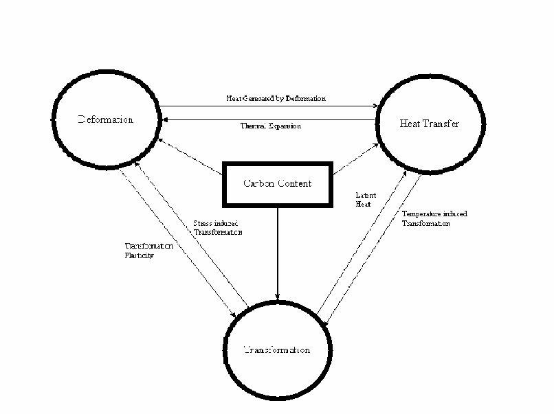
Figure 1: Relationship between various DEFORM modules.
1.3. A nalyzing manufacturing processes with DEFORM
DEFORM can be used to an alyze most thermo-mechanical forming processes, and many heat treatment processes. The general approach is to define the geometry and material of the initial work piece in DEFORM, then sequentially simulate each process that is to be applied to the work piece.
The recommended sequence for designing a manufacturing process using DEFORM
Define your proposed process
Final forged part geometry
Material
Tool progressions
Starting work piece/billet geometry
Processing temperatures, reheats, etc.
Gather required data
Material data
Processing condition data
Using the DEFORM pre-processor, input the problem definition for the first operation
Submit the data for simulation
Using the DEFORM post-processor, review the results
Repeat the preprocess-simulate-review sequence for each operation in the process
If the results are unacceptable, use your engineering experience and judgment to modify the process and repeat the simulation sequence.
1.4. Before you begin
Before you begin work on your DEFORM simulation, spend some time planning the simulation. Consider the type of information you hope to gain from the an alysis. Are temperatures important? What about die fill? Press loads? Material deformation patterns? Ductile fracture of the part? Die failure? Buckling? Can the part be modeled as a two dimensional part, or is a three dimensional simulation necessary? Having a definite goal will help you design a simulation which will provide the information most vital to understanding your manufacturing process.
1.5. Geometry representation
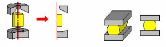
Figure 2: Axisymmetric and plane strain examples.
DEFORM simulations can be run either as two dimensional (2D, PC, Pro) or three dimensional (3D) models. In general, 2D models are smaller, easier to set up, and run more quickly than 3D models. Frequently, the added detail of a 3D model is not worth the additional time required over a 2D simulation if the
process can reasonably be represented in 2D.
There are two 2D geometry representations: axisymmetric and plane strain. Axisymmetric geometries assume that the geometry of every plane radiating out from the centerline is identical. Plane strain requires that there is no material flow in the out of plane direction, and that flow in every plane parallel to the section modeled is identical. Figure 2 illustrates axisymmetric and plane strain models. Objects that are closely approximated by axisymmetric or plane strain models can also be modeled in 2D by neglecting minor variations. For example, if the head shape is not critical a hex head bolt can be modeled as axisymmetric by defining a head radius which maintains constant volume (radius =0.525*(distance across flats)). A gradually tapering part such as a turbine blade can be modeled by modeling several plane strain sections.
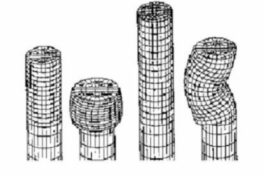
Figure 3: Buckling.
Buckling of cylindrical parts is a fully three dimensional process, and must be modeled as such if such behavior is expected. An axisymmetric simulation will not show buckling, even if it will occur in the actual process (Figure3).
Parts which cannot be simplified to 2D must be modeled as 3D.
1.6. The DEFORM system
The DEFORM system consists of three major components:
1. A pre-processor for creating, assembling, or modifying the data required to an alyze the simulation, and for generating the required database file.
2. A simulation engine for performing the numerical calculations required to a nalyze the process, and writing the results to the database file. The simulation engine reads the database file, performs the actual solution calculation, and appends the appropriate solution data to the database file. The simulation engine also works seamlessly with the Automatic Mesh Generation (AMG) system to generate a new FEM mesh on the work piece whenever necessary. While the simulation engine is running, it writes status information, including any error messages, to the message
(.MSG) and log (.LOG) files.
3. A post-processor for reading the database file from the simulation engine and displaying the results graphically and for extracting numerical data.
1.7. Pre-processing
The DEFORM preprocessor uses a graphical user interface to assemble the data required to run the simulation. Input data includes
Object description
Includes all data associated with an object, including geometry, mesh, temperature, material, etc.
Material data
Includes data describing the behavior of the material under the conditions which it will reasonably experience during deformation.
Inter object conditions
Describes how the objects interact with each other, including contact, friction, and heat transfer between objects.
Simulation controls
Includes instructions on the methods DEFORM should use to solve the problem, including the conditions of the processing environment, what physical processes should be modeled, how many discrete time steps should be used to model the process, etc.
Inter material data
Describes the physical process of one phase of a material transforming into other phases of the same material in a heat treatment process. For example, the transformation of austenite into pearlite, banite, and martensite.
1.8. Creating input data
There are several ways to enter data into the DEFORM pre-processor.
Depending on the requirements of a particular problem, a combination of the following methods will frequently be used.
Manual input
The pre-processor menus contain input fields for nearly every possible data input in DEFORM. The user can enter, view, or edit any of these values. Discussions of each field are contained in the reference section of this manual.
Keyword file input
Most of the data fields in the DEFORM pre-processor correspond directly to a DEFORM keyword. Individual keywords describe very specific information about a particular object characteristic, simulation control, material characteristic, or inter-object relationship. Keyword data can be saved in a keyword (.KEY) file. A keyword file is a human readable (ASCII) representation of DEFORM simulation data.
The typical format of a keyword is:
[keyword name] [keyword parameters] [default data] [data]
[data]
A keyword file may contain a complete simulation data set, or it may contain only one or a few specific keywords.
Assembling keyword files
When a keyword file is read into the pre-processor, only the specific data fields listed in that keyword are changed; the remainder is unchanged. Thus, it is possible to assemble a complete set of problem data by loading one keyword file that contains only data for one object, another keyword file that contains material data, etc.
To save specific elements of a keyword file, it is necessary to save the entire file, then use a text editor such as Notepad, vi, emacs, or equivalent to delete unwanted information. The keyword file load and save features on the main pre- processor menu load or save an entire data set. To load partial keyword files, use the Keyword, Load option from the File menu.
Other file inputs
Various data types, particularly part geometries and material data, can be read from appropriate format files.
Modifying problem data
Solution or input step data from any stored step in a database file can be read into the pre-processor, modified, and either appended to an existing database, or written to a new database file.
Viewing specific problem data
Most problem data stored in the database file is accessible in the post-processor. However, certain specific information such as boundary conditions or inter-object contact conditions is displayed differently in the pre-processor. When debugging a problem which is not running properly, it is sometimes useful to use the pre-processor data display to view this information.
详细内容请见附件
免责声明:
本页面/内容部分素材来源于互联网公 开 信 息,旨在传递更多信息,不代表本平台立场。
版权归原作者或机构所有,如涉及侵权,请通过平台联系我们,我们将在核实后第一时间处理。
本平台对转载内容的真实性、准确性不作任何保证,用户需自行判断并承担使用风险。