AS ME VIII2-2025 5.3防止局部失效
下面是AS ME VIII2-2025中的一段原话,我们翻译一下,然后重点说一下需要注意的地方。
5.3 PROTECTION AGAINST LOCAL FAILURE5.3.1.1 A nalysis Requirements Based on Design Rules. In addition to demonstrating protection against plastic col lapse as defined in 5.2, the applicable local failure criteria below shall be satisfied for a component. These requirements apply to all components where the thickness and configuration of the component are established by using design-by an alysis rules. It is not necessary to evaluate protection against local failure, if the component design is in accordance with Part 4 (e.g., component wall thickness and weld detail per 4.2). 5.3.1.2 Methods of An alysis. Two an alysis methods are provided for evaluating protection against local failure un der applied design loads. When protection against plastic collapse is satisfied by the method in 5.2.3, either method listed below is acceptable. (a) The elastic ana lysis procedure in 5.3.2 provides an approximation of the protection against local failure based on the results of an elastic an alysis. (b) Amoreaccurateestimate of theprotection against local failure of a component is obtained using the elastic–plastic stress an alysis procedures in 5.3.3. 5.3.2 ELASTIC AN ALYSIS — TRIAXIAL STRESS LIMIT The algebraic sum of the three linearized primary principal stresses, as shown in eq. (5.6), from Design Load Combi nation (1) of Table 5.3 shall be used for checking this criterion. 5.3.3 ELASTIC–PLASTIC AN ALYSIS — LOCAL STRAIN LIMIT 5.3.3.1 Assess ment Procedure for a Set of Applied Loads. The following procedure shall be used to evaluate pro tection against local failure for a set of applied loads: Step 1.Perform an elastic–plastic stress an alysis based on the load case combinations for the local criteria given in Table 5.5. The effects of nonlinear geometry shall be considered in the an alysis. Step 2.For each point in the component, determine the principal stresses, σ1, σ2, σ3; the equivalent stress, σe, using eq. (5.1); and the equivalent plastic strain, εpeq. Step 3.Determine the limiting triaxial strain, εL, using eq. (5.7) where εLu, m2, and αsl are determined from Table 5.7.  Step 4.Determine the forming strain εcf based on the material and fabrication method in accordance with Part 6. If heat treatment is performed in accordance with Part 6, the forming strain may be assumed to be zero. Step 5.Determine if the strain limit is satisfied. The component is acceptable for the specified load case if eq. (5.8) is satisfied.
5.3 防止局部失效
5.3.1 概述
5.3.1.1 基于设计规则的分析要求
构件除满足 5.2 节规定的防止塑性垮塌要求外,还应满足下述适用的局部失效准则。当构件厚度与结构形式是按分析设计规则确定时,本要求适用于所有构件。若构件设计符合第4 篇要求(例如按 4.2 确定的壁厚及焊接细节),则无需进行防止局部失效的评定。
5.3.1.2 分析方法
本节提供两种分析方法,用于评定设计载荷作用下构件的防止局部失效能力。若已通过 5.2.3 节方法满足防止塑性垮塌要求,则以下任一方法均可采用:(a) 5.3.2 弹性分析方法:基于弹性分析结果,近似评定防止局部失效能力。(b) 5.3.3 弹塑性应力分析方法:可更精确地评定构件防止局部失效的能力。
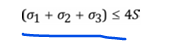
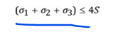
5.3.2 弹性分析 —— 三向应力限值
应采用 ** 表 5.3 设计载荷组合(1)** 下,经线性化处理后的三个主一次主应力的代数和(见公式 5.6)对本准则进行校核
5.3.3 弹塑性分析 —— 局部应变限值
5.3.3.1 一组外加载荷的评定程序
对一组外加载荷进行防止局部失效评定时,应采用以下程序:
步骤 1根据表 5.5 中给出的局部准则对应的载荷组合,进行弹塑性应力分析。分析中应考虑几何非线性效应。
步骤 2对构件内的每个计算点,确定主应力σ1, σ2, σ3;按公式 (5.1) 计算当量应力σe;并确定当量塑性应变εpeq。
步骤 3按公式 (5.7) 确定极限三向应变εL,其中εLu、m2 和αsl 由表 5.7 查取。
步骤 4根据材料和制造工艺,按第6篇确定成形应变εcf。若按第6篇进行了热处理,则成形应变可取为零。
步骤 5判定是否满足应变限值要求。若满足公式 (5.8),则构件在该指定工况下评定合格。
总结:评定方法由三向应力和三向应变,弹塑性计算需要采用真实的应力应变曲线,这时你会发现局部应变的大小是多少。你会发现采用第4篇是否需要再进行计算。你会发现很多是标准里面没有说的,大家慢慢体会。