汽车排气歧管仿真(shell模型)

Simcenter STAR-CCM+ 为那些在模拟期间最适合用单层网格表示的薄壁结构提供支持。这些单层网格被称为Shell。
在本教程中,您将研究响应于进入入口的热气体,排气系统薄壁上的温度分布。您将使用shell单元来表示排气系统的壁面。下图显示了案例设置的示意图。
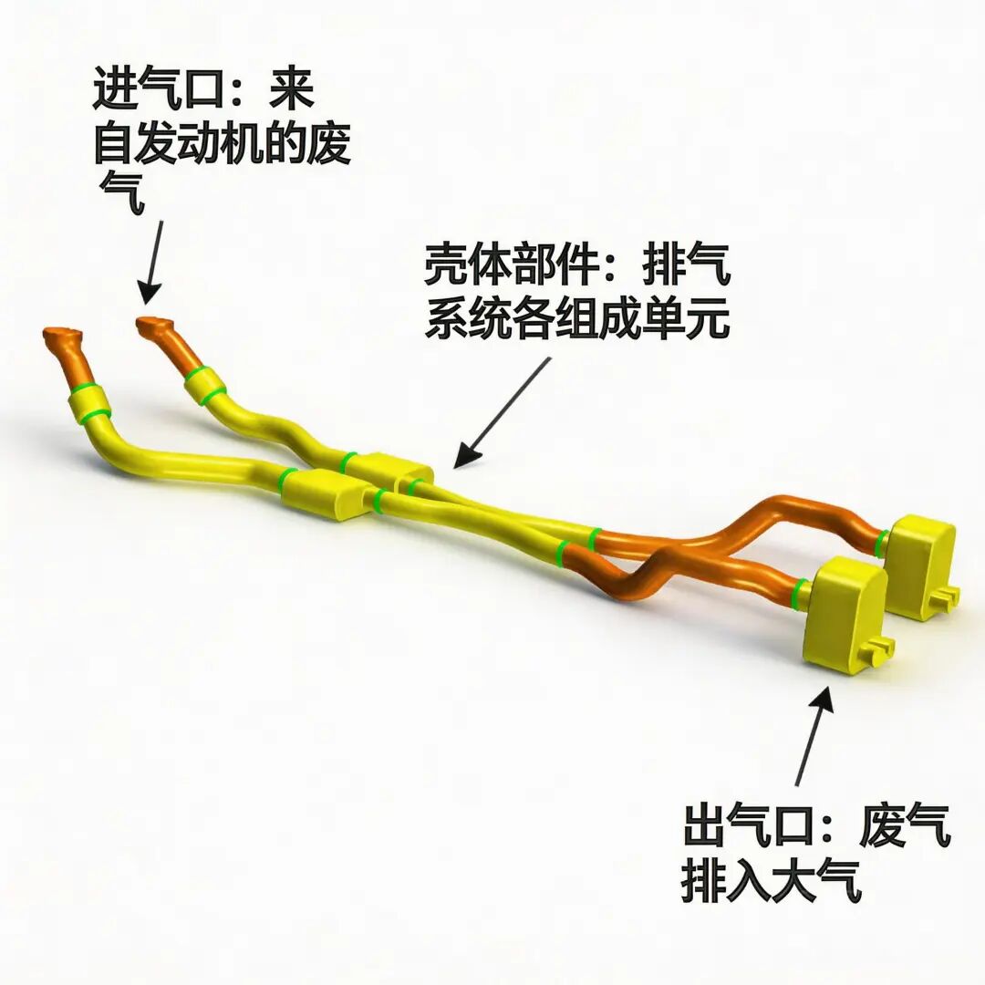
为了准备本教程的几何模型,您首先将排气歧管的 CAD 模型导入 3D-CAD 几何建模器。3D-CAD 提供了一套工具,帮助您准备 CAD 模型,使其适合进行模拟。下图显示了本模拟中使用的几何模型。
在几何部件层面,您将排气歧管的片体转换为shell部件。当您在shell部件上创建网格时,会得到一个单层厚的网格层,您可以在其上求解这些部件的物理场。使用shell单元的主要优势之一是它减少了模拟所需的计算时间和资源。
除了演示 CAD 准备和体网格划分步骤外,本教程还说明了如何为使用薄壁结构的 CHT 模拟设置必要的交界面、物理模型和边界条件。
注:本文采用STAR-CCM+ 17.06演示导入几何模型
在本教程中,您将获得一个排气歧管 CAD 模型。您将几何模型直接导入 3D-CAD,这样您可以在继续设置 Geometry > Parts 之前进行更改。
要将排气几何模型导入 3D-CAD:
创建一个新的 Simcenter STAR-CCM+ 模拟。 选择 File > Import > Import CAD Model into 3D-CAD…。 在 Open 对话框中,导航到下载的教程包中的 heatTransferAndRadiation文件夹。请参阅从支持中心门户网站下载教程文件。选择 exhaust pipe.x_t,然后点击 Open。将 3D-CAD Model 1 节点重命名为 Exhaust Pipe。将模拟保存为 PartsBasedShells.sim。
为模拟准备排气几何模型
使用 3D-CAD 中的工具清理并准备用于模拟的排气歧管。这些准备工作包括填充端部孔洞和封闭间隙。
右键单击 Exhaust Pipe 节点并选择 (Check Validity)。有效性检查的结果消息将打印在 Output 窗口中。在本例中,将显示以下消息:
All bodies of model are valid.
使用 Fill Surface 操作来封闭入口和出口:
a) 在 Graphics 窗口中,选择包围第一个入口的边缘。您可以双击单个自由边,以自动选择与其连接的所有自由边。
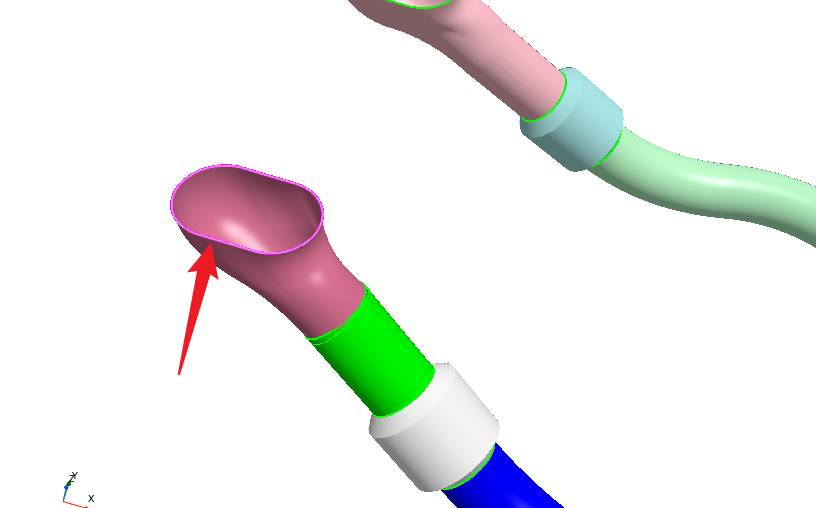
b) 右键单击其中一条边缘并选择 Fill Surface。Fill Surface 面板出现在 Graphics 窗口的左侧。
c) 在 Fill Surface 面板中,点击 OK。
入口孔被一个曲面填充。
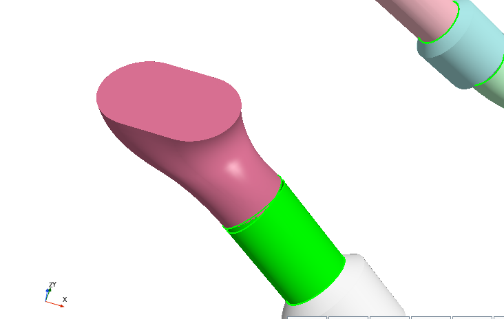
d) 重复上述步骤以填充第二个入口。
e) 按照下图中的标签,将入口面分别重命名为
Inlet 1和Inlet 2。
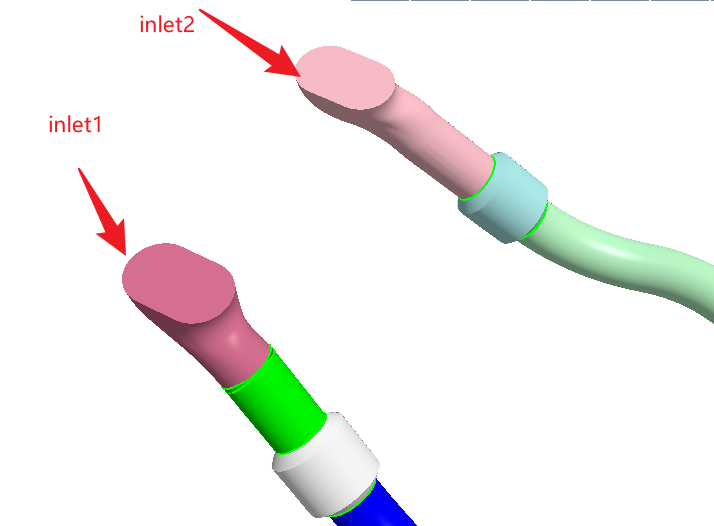
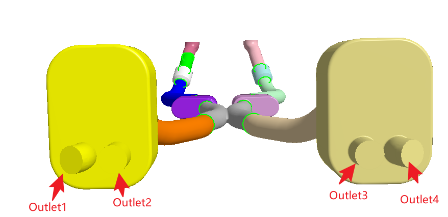
f) 重复相同的过程来填充出口的孔。根据下图,将出口面重命名为 Outlet 1、Outlet 2、Outlet 3 和 Outlet 4。
使用 Search 工具在整个几何体上进行搜索,以查找相互干涉的几何体。
要搜索相交的几何体:
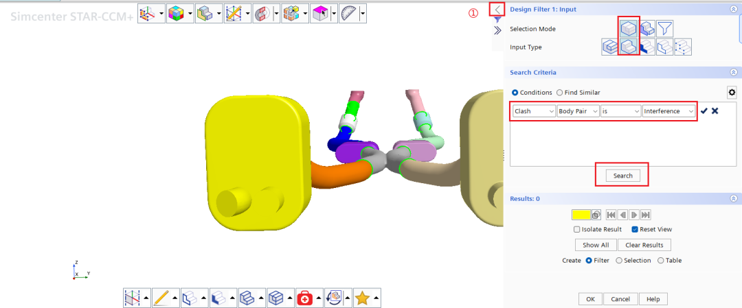
冲突的几何体将显示在图形窗口中。
以表格形式显示结果以识别哪些几何体存在冲突:
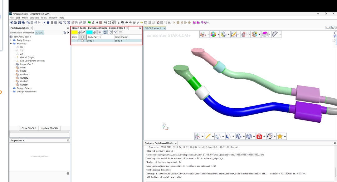
在 Vis 工具栏中,点击 (Save-Restore-Select Views) 并选择 Views > -Y。
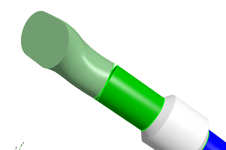
如果放大 Inlet 1,您可以看到 Body 1 和 Body 3 之间存在间隙。
关闭表格和 Search Tool。 在 Results 面板中,在 Create 旁边,选择 Table 并点击 OK。默认情况下,结果表出现在 3D-CAD 模拟树和 3D-CAD View 场景之间。
对于本教程,您将使用 Bridge Surface 工具封闭间隙。由于 Body 1 的部分表面与 Body 3 相交,您必须在 Body 1 和 Body 3 上创建平面切割。这些切割会移除重叠的表面,并为 Bridge Surface 工具提供均匀的边缘以生成表面。
为了隔离需要修复的部件,在 Body Groups 节点下,多选 Body 1 和 Body 3,右键单击并选择 Show Only。
要切割 Body 1:
a) 右键单击 Body 1(直管短段)上离 Body 3 最远的边缘,选择 Reference Geometry > Plane from Curve。
b) 在 Plane from Curve 面板中,将 Type 设置为 Fitting Plane 并点击 OK。c) 在特征树中,右键单击 Plane 1 并选择 Reference Geometry > Plane by Transformation。
d) 在 Plane by Transformation 面板中,为 Translation Vector 的 Z 分量输入-0.095并点击 OK。
e) 展开 Body Groups 节点,右键单击 Body 1,并选择 Boolean > Slice。
f) 在 Slice 面板中,设置以下参数:
| Keep Side | |
| Sketch Planes |
g) 点击 OK。
要切割 Body 3:
a) 在特征树中,右键单击 Plane 2 并选择 Reference Geometry > Plane by Transformation。
b) 在 Plane by Transformation 面板中,为 Translation Vector 的 Z 分量输入-0.0150并点击 OK。
c) 展开 Body Groups 节点,右键单击 Body 3,并选择 Boolean > Slice。
d) 在 Slice 面板中,设置以下参数:参数 设置 Keep Side Back Side Sketch Planes Plane 3 e) 点击 OK。
要封闭间隙:
a) 在特征树中,多选 Plane 1、Plane 2 和 Plane 3。
b) 右键单击所选内容并选择 Hide。
c) 在图形窗口中,多选 Body 1 和 Body 3 之间间隙两侧的自由边。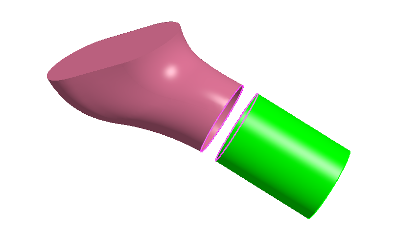
d) 右键单击所选内容并选择 Bridge Surface。
e) 在 Bridge Surface 面板中,激活以下选项:
| Tangent to Faces for Source Edges |
| Tangent to Faces for Target Edges |
| Sew Bodies |
操作的预览将显示在 3D-CAD View 场景中。
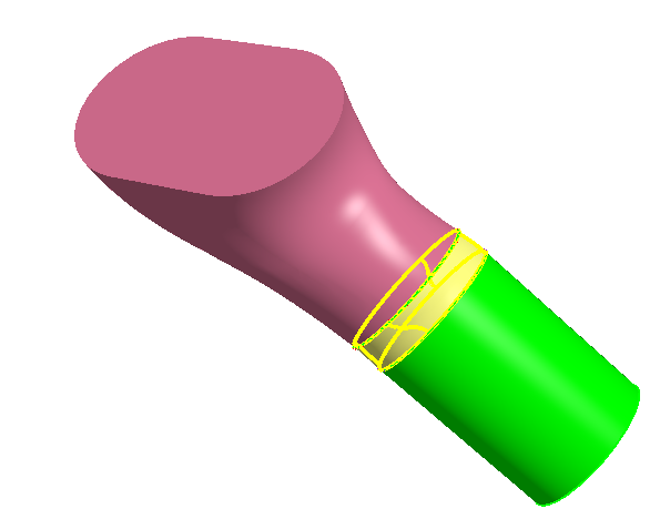
f) 点击 OK。
右键单击 3D-CAD View 场景中的空白区域,然后选择 Restore > Hidden Bodies。
几何模型现在已准备就绪,您可以退出 3D-CAD。
点击对象树底部的 Close 3D-CAD 按钮。
注意: 退出 3D-CAD 时,3D-CAD View 场景会自动关闭。
保存模拟。
创建shell部件
要创建 shell 部件:
右键单击 Geometry > 3D-CAD Models > Exhaust Pipe 节点并选择 New Geometry Part。 在 Part Creation Options 对话框中,激活 Create Shells From Sheets 并点击 OK 接受设置。来自 3D-CAD 模型的片体将被转换并作为 shell 部件添加到 Geometry > Parts 节点下。
一些排气表面用于最终模拟中的流动边界条件。这些表面必须转换为常规部件(而非 shell 部件)。
要将入口和出口从 shell 部件转换为常规(实体)部件:
a) 展开 Geometry > Parts > Body 1 > Surfaces 节点并选择
Inlet 1 [Back]和Inlet 1 [Front]。
b) 右键单击所选内容并选择 Create New Part From Surfaces。一个新部件被创建并添加到 Parts 节点。
c) 右键单击该 Part 并选择 Convert to Solid。
d) 将新创建的 Part 重命名为Inlet 1。
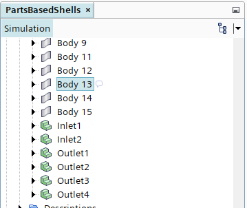
e) 以相同的方式,将剩余的入口和出口转换为实体部件。下表指定了每个入口和出口的位置。位置 入口和出口表面 Body 8 Inlet 2 [Back] 和 Inlet 2 [Front] Body 4 Outlet 1 [Back] 和 Outlet 1 [Front] Body 4 Outlet 2 [Back] 和 Outlet 2 [Front] Body 12 Outlet 3 [Back] 和 Outlet 3 [Front] Body 12 Outlet 4 [Back] 和 Outlet 4 [Front] 实体部件列在 Geometry > Parts 节点下,如下所示。
右键单击 Scenes 节点并选择 New Scenes > Geometry。一个新的几何场景 Geometry Scene 1 被添加到 Scenes 节点。此场景将自动显示 Geometry > Parts 节点下列出的所有部件。
为流体体积创建一个形状部件:
a) 右键单击 Geometry > Parts 节点并选择 New Shape Part > Block。
b) 在 Create Block Part 面板中,设置以下参数(先设置 Corner 2):参数 设置 Corner 1 [-2, -1, -1] m Corner 2 [4, 1, 1] m c) 点击 Create,然后点击 Close。
一个形状部件 Block 被创建并添加到 Parts 节点。
d) 将 Geometry > Parts > Block 节点重命名为Fluid Volume。拆分 Fluid Volume 的表面以便识别边界:
a) 右键单击 Geometry > Parts > Fluid Volume > Surfaces > Block Surface 节点并选择 Split by Angle。
b) 在 Split Part Surfaces by Angle 对话框中,点击 OK。
c) 将
Block Surface 3重命名为Inlet,将Block Surface 6重命名为Outlet。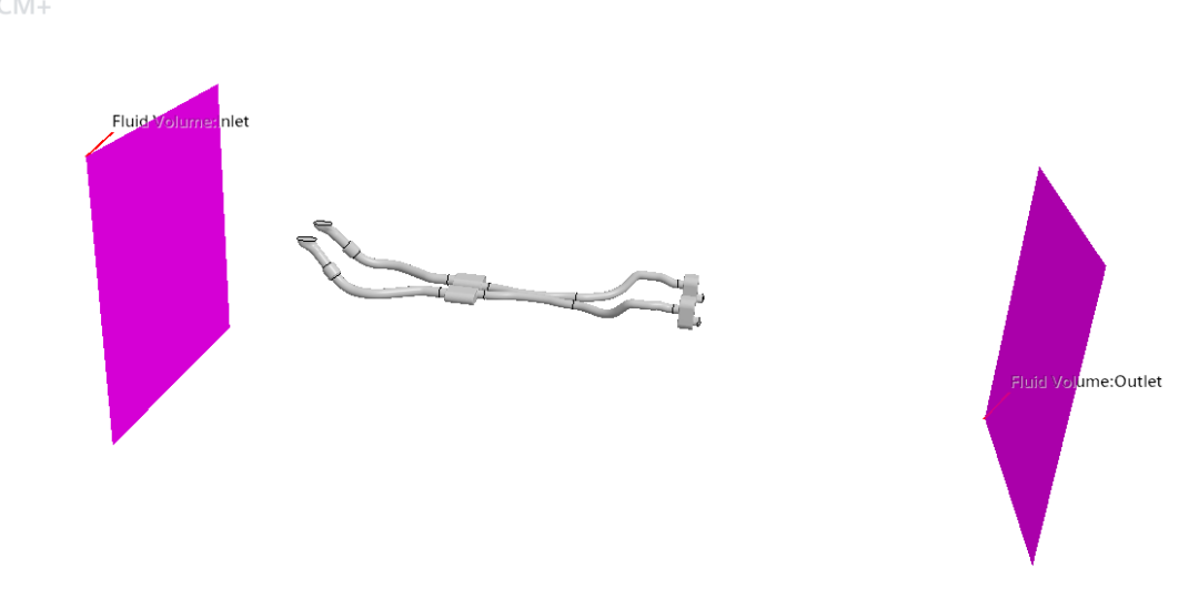
保存模拟。
包面处理并检测接触
为 shell 部件创建 Zip Edges 操作:
a) 右键单击 Geometry > Operations 节点并选择 New > Surface Preparation > Zip Edges。
b) 在 Create Zip Edges Operation 对话框中,选择所有 shell 部件并点击 OK。
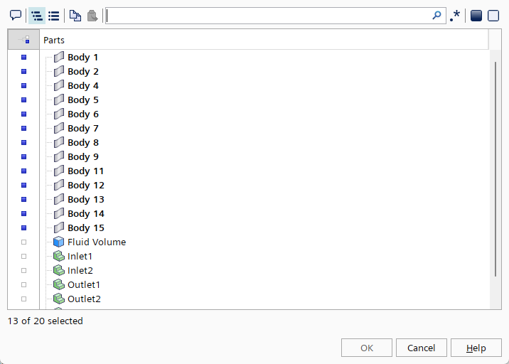
c) 选择 Operations > Zip Edges 节点并将 Zip Mode 设置为 New Description - Discrete(确认选择)。
Zip Edges 操作仅在您将 Zip Mode 设置为 New Description - Discrete 时支持 shell 部件。
d) 右键单击 Geometry > Operations > Zip Edges 节点并选择 Execute。
为流体体积设置一个包面网格操作:
a) 右键单击 Geometry > Operations 节点并选择 New > Surface Preparation > Surface Wrapper。
b) 在 Create Surface Wrapper Auto Mesh Operation 对话框中,选择所有部件并点击 OK。
c) 将 Surface Wrapper 节点重命名为 Surface Wrapper (All Parts)。
d) 选择 Surface Wrapper (All Parts) 节点并激活以下属性:
Create Weak Contacts With Input PartsLink Output Part Name(确认选择)
e) 选择 Surface Wrapper (All Parts) > Default Controls > Base Size 节点并将 Value 设置为 0.025 m。
f) 创建并定义一个自定义表面控制,为流体体积指定一个粗网格:
右键单击 Surface Wrapper (All Parts) > Custom Controls 节点并选择 New > Surface Control。 将 Surface Control 重命名为 Surface Control (Fluid Volume)。选择 Surface Control (Fluid Volume) 节点并点击 Part Surfaces 的自定义编辑器。 在 Surface Control (Fluid Volume) - Part Surfaces 对话框中,选择 Fluid Volume并点击 OK。编辑 Surface Control (Fluid Volume) 节点并按如下所示设置自定义控制设置:
| Controls | Target Surface Size | Target Surface Size |
| Controls | Minimum Surface Size | Minimum Surface Size |
| Values | Target Surface Size | Size Type |
| Values | Minimum Surface Size | Size Type |
g) 右键单击 Geometry > Operations > Surface Wrapper (All Parts) 节点并选择 Execute。
为排气歧管设置一个包面网格操作:
a) 右键单击 Geometry > Operations 节点并选择 New > Surface Preparation > Surface Wrapper。
b) 在 Create Surface Wrapper Auto Mesh Operation 对话框中,选择除
Fluid Volume和Surface Wrapper (All Parts)之外的所有部件,然后点击 OK。c) 将 Surface Wrapper 节点重命名为
Surface Wrapper (Exhaust)。d) 选择 Surface Wrapper (Exhaust) 节点并激活以下属性:
Create Weak Contacts With Input PartsLink Output Part Name(确认选择)e) 选择 Surface Wrapper (Exhaust) > Default Controls > Base Size 节点并将 Value 设置为
0.02 m。f) 右键单击 Geometry > Operations > Surface Wrapper (Exhaust) 节点并选择 Execute。
在排气歧管和流体体积之间创建一个弱接触创建器操作:
a) 右键单击 Geometry > Operations 节点并选择 New > Surface Preparation > Contact Creator。
b) 在打开的对话框中,选择Surface Wrapper (All Parts)和Surface Wrapper (Exhaust),然后点击OK。
c) 右键点击Geometry→Operations,执行所有。
保存模拟。
创建区域和交界面
本模拟需要三个区域:包围排气歧管的流体区域、用于管内废气的流体区域以及用于 shell 部件的固体区域。为了在区域之间传递热信息,您必须手动创建交界面。
对于此模拟,您将创建四个交界面:
废气与流体体积之间的交界面 废气与 shell 部件之间的交界面 shell
部件与流体体积之间的交界面 用于 shell 部件的枢纽交界面
为流体体积创建一个区域:
a) 右键单击 Geometry > Parts > Surface Wrapper (All Parts) 节点并选择 Set New Region…。
b) 将 New Region Name 设置为Fluid并点击 OK。
c) 展开 Regions > Fluid > Boundaries 节点。
d) 将 Default 节点重命名为Fluid Wall。
e) 右键单击 Boundaries 节点并创建一个名为Inlet的新边界。
f) 对于 Inlet 边界,设置以下属性:属性 设置 Part Surfaces Fluid Volume > Inlet Type Velocity Inlet g) 按照相同的过程,创建一个名为
Outlet的边界并设置以下属性:属性 设置 Part Surfaces Fluid Volume > Outlet Type Pressure Outlet 为废气创建一个区域:
a) 右键单击 Geometry > Parts > Surface Wrapper (Exhaust) 节点并选择 Set Region > New…。
b) 将 New Region Name 设置为Exhaust Gas并点击 OK。
c) 展开 Regions > Exhaust Gas > Boundaries 节点。
d) 右键单击 Boundaries 节点并创建一个名为Inlets的新边界。
e) 对于 Inlets 边界,设置以下属性:属性 设置 Part Surfaces 选择 Inlet 1 和 Inlet 2 Type Mass Flow Inlet f) 按照相同的过程,创建一个名为
Outlets的边界并设置以下属性:属性 设置 Part Surfaces 选择 Outlet 1, Outlet 2, Outlet 3 和 Outlet 4 Type Wall 为 shell 部件创建一个区域:
a) 右键单击 Regions 节点并选择 New > Shell Region。
b) 将节点重命名为Shells。
c) 选择 Regions > Shells 节点并点击 Parts 的自定义编辑器。
d) 在 Shells - Parts 对话框中,选择所有 shell 部件并点击 OK。
本模拟要求您手动创建四个交界面。
在流体和废气之间创建一个交界面:
a) 展开 Regions 节点并多选 Fluid 和 Exhaust Gas 区域。
b) 右键单击其中一个节点并选择 Create Interface > Contact-Mode Boundary Interface。
c) 选择 Interfaces > Fluid/Exhaust Gas 节点并点击 Contacts 的自定义编辑器。
d) 在 Fluid/Exhaust Gas - Contacts 对话框中,在 Filter by Path 文本框中输入Outlet,然后从结果中选择以下接触:属性 选择 Contacts Outlet 1. Outlet 1/Outlet 1.Outlet 1
Outlet 2. Outlet 2/Outlet 2.Outlet 2
Outlet 3. Outlet 3/Outlet 3.Outlet 3
Outlet 4. Outlet 4/Outlet 4.Outlet 4e) 点击 OK。
在流体和 shell 部件之间创建一个交界面:
a) 展开 Regions 节点并多选 Fluid 和 Shells 区域。
b) 右键单击其中一个节点并选择 Create Interface > Contact-Mode Boundary Interface。
c) 选择 Interfaces > Fluid/Shells 节点并点击 Contacts 的自定义编辑器。
d) 在 Fluid/Shells - Contacts 对话框中,选择所有接触并点击 OK。
e) 选择 Interfaces > Fluid/Shells 节点并将 Type 设置为 Mapped Contact Interface。在废气和 shells 之间创建一个交界面:
a) 展开 Regions 节点并多选 Exhaust Gas 和 Shells 区域。
b) 右键单击其中一个节点并选择 Create Interface > Contact-Mode Boundary Interface。
c) 选择 Interfaces > Exhaust Gas/Shells 节点并点击 Contacts 的自定义编辑器。
d) 在 Exhaust Gas/Shells - Contacts 对话框中,选择所有接触并点击 OK。
e) 选择 Interfaces > Exhaust Gas/Shells 节点并将 Type 设置为 Mapped Contact Interface。
对于此模拟,您创建一个枢纽交界面,以便可以在 shell 部件之间传递热数据。
为 shell 部件创建一个枢纽交界面:
a) 右键单击 Interfaces 节点并选择 New Hub Interface > Curve-Mode。
b) 将节点重命名为Shells/Shells Hub。保存模拟。
准备并生成网格
将部件分配给区域并创建交界面后,您可以定义体网格的设置。
对于此模拟,Trimmed Cell Mesher 与 Pris m Layer Mesher 结合使用,为流体体积构建合适的网格。要设置并生成体网格:
a) 右键单击 Geometry > Operations 节点并选择 New > Mesh > Automated Mesh。
b) 在 Create Automated Mesh Operation 对话框中:
分组 网格生成器 Surface Meshers Surface Remesher Core Volume Meshers Trimmed Cell Mesher Optional Boundary Layer Meshers Pris m Layer Mesher c) 选择 Automated Mesh > Meshers > Trimmed Cell Mesher 节点并激活 Perform Mesh Alignment。
d) 将 Automated Mesh 节点重命名为
Automated Mesh (Fluid)。e) 编辑 Automated Mesh (Fluid) > Default Controls 节点并设置以下属性:
节点 属性 设置 Base Size Value 0.025 m Number of Pris m Layers Number of Pris m Layers 4 Pris m Layer Stretching Pris m Layer Stretching 1.3 Pris m Layer Total Thickness Size Type Relative to Base Pris m Layer Total Thickness Percentage of Base 25 f) 为流体体积创建一个表面控制:
节点 属性 设置 Controls Target Surface Size Target Surface Size = Custom Controls Minimum Surface Size Minimum Surface Size = Custom Values Target Surface Size Size Type = Relative to base, Percentage of Base = 500 Values Minimum Surface Size Size Type = Relative to base, Percentage of Base = 300 右键单击 Geometry > Operations > Automated Mesh (Fluid) > Custom Controls 节点并选择 New > Surface Control。 选择 Surface Control 节点并点击 Part Surfaces 的自定义编辑器。 在 Surface Control - Part Surfaces 对话框中,选择 Surface Wrapper (All Parts) > Fluid Volume并点击 OK。编辑 Surface Control 节点并按如下所示设置自定义控制设置: 点击 OK。 在 Parts 列表中,选择 Surface Wrapper (All Parts)。在 Select Meshers 中,按顺序选择以下网格生成器:
对于排气歧管内部的网格,使用 Polyhedral Mesher 与 Pris m Layer Mesher 结合。
为排气歧管定义体网格:
a) 右键单击 Geometry > Operations 节点并选择 New > Mesh > Automated Mesh。
b) 在 Create Automated Mesh Operation 对话框中:
分组 网格生成器 Surface Meshers Surface Remesher Core Volume Meshers Polyhedral Mesher Optional Boundary Layer Meshers Pris m Layer Mesher c) 将 Automated Mesh 节点重命名为
Automated Mesh (Exhaust)。d) 编辑 Automated Mesh (Exhaust) > Default Controls 节点并设置以下属性:
节点 属性 设置 Base Size Value 0.02 m Number of Pris m Layers Number of Pris m Layers 4 Pris m Layer Stretching Pris m Layer Stretching 1.3 Pris m Layer Total Thickness Size Type Relative to Base Pris m Layer Total Thickness Percentage of Base 25 点击 OK。 在 Parts 列表中,选择 Surface Wrapper (Exhaust)。在 Select Meshes 中,按顺序选择以下网格生成器:
对于 shell 部件,您定义一个生成四边形网格的 shell 网格操作。
为 shell 部件定义网格:
a) 右键单击 Geometry > Operations 节点并选择 New > Mesh > Automated Mesh (Shell)。
b) 在 Parts 列表中,选择所有 shell 部件。
c) 在 Select Meshers 中,选择 Quadrilateral Mesher。
d) 点击 OK。
e) 选择 Geometry > Operations > Automated Mesh (Shell) > Default Controls > Base Size 节点并将 Value 设置为0.02 m。
现在所有网格设置都已定义,您可以生成体网格了。
在工具栏中点击 (Generate Volume Mesh),或选择 Mesh 菜单中的 Generate Volume Mesh。网格生成器的运行和进度将显示在 Output 窗口中。
要显示体网格,请在 Vis 工具栏中点击 (Create/Open Scenes) 并选择 Mesh。
保存模拟。
选择物理模型
物理模型定义了模拟中的物理变量和现象。本模拟需要两个物理连续体——一个用于气体区域,一个用于 shell 区域。
要定义物理连续体:
将现有的连续体 Continua > Physics 1 重命名为
Fluid。创建一个新的物理连续体,命名为
Solid Shells。选择 Regions > Shells 节点并将 Physics Continuum 设置为
Solid Shells。
Fluid 物理连续体已分配给 Fluid 和 Exhaust Gas 区域。
在此模拟中,您将气体建模为湍流空气,以 450°C 的温度进入入口。要指定定义气体行为的模型:
右键单击 Continua > Fluid 节点并选择 Select Models…。
在 Fluid Model Selection 对话框中,按顺序选择以下模型:
分组框 模型 Space Three-Dimensional (already selected) Time Steady Material Gas Flow Segregated Flow Enabled Models Gradients (selected automatically) Equation of State Ideal Gas Energy Segregated Fluid Temperature Viscous Regime Turbulent Turbulence Reynolds-Averaged Navier-Stokes (selected automatically) Reynolds-Averaged Turbulence K-Epsilon Turbulence Enabled Models Realizable K-Epsilon Two-Layer (selected automatically) Enabled Models Two-Layer All y+ Wall Treatment (selected automatically) Enabled Models Wall Distance (selected automatically) 选择 Fluid > Initial Conditions > Static Temperature 节点并将 Value 设置为
25.0 C。选择 Fluid > Initial Conditions > Velocity 节点并将 Value 设置为
[1.0, 0.0, 0.0] m/s。
指定定义固体 shells 的物理模型。
右键单击 Continua > Solid Shells 节点并选择 Select Models…。
在 Solid Shells Model Selection 对话框中,按顺序选择以下模型:
分组框 模型 Space Shell Three Dimensional Time Steady Material Solid Optional Models Segregated Solid Energy Equation of State Constant Density 选择 Solid Shells > Initial Conditions > Static Temperature 节点并将 Value 设置为
25.0 C。
为模拟定义物理连续体后,检查交界面。
要显示 shell 部件之间的交界面:
a) 打开 Geometry Scene 1。
b) 右键单击 Interfaces > Shells/Shells_Hub 节点并选择 Initialize。
c) 选择 Shells/Shells_Hub 节点。shell 部件之间的交界面将在图形窗口中高亮显示。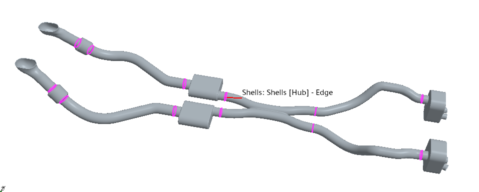
保存模拟。
设置边界条件
定义热分析的边界条件。
设置入口处气体的质量流量和温度:
a) 编辑 Regions > Exhaust Gas > Boundaries > Inlets > Physics Values 节点并设置以下属性:
节点 属性 设置 Mass Flow Rate Value 0.05 kg/s Total Temperature Value 450 C 设置流体区域的边界条件:
a) 编辑 Regions > Fluid > Boundaries > Inlet > Physics Values 节点并设置以下属性:
节点 属性 设置 Static Temperature Value 25.0 C 保存模拟。
运行模拟
在运行模拟之前,您需要定义停止准则。建议在多核机器(四核)上运行本教程。
在多核上运行:
a) 保存模拟,然后关闭 Simcenter STAR-CCM+。
b) 再次启动 Simcenter STAR-CCM+ 并选择 File > Load。
c) 在 Load a File 对话框中,激活 Parallel on Local Host 并将 Compute Processes 设置为4。
d) 点击 Browse 并选择之前保存的PartBasedShells.sim文件。
e) 点击 OK。在模拟树中,编辑 Stopping Criteria 节点并设置以下属性:
节点 属性 设置 Maximum Steps Enabled Activated Maximum Steps Value 500
要运行模拟:
在 Solution 工具栏中点击 (Run)。
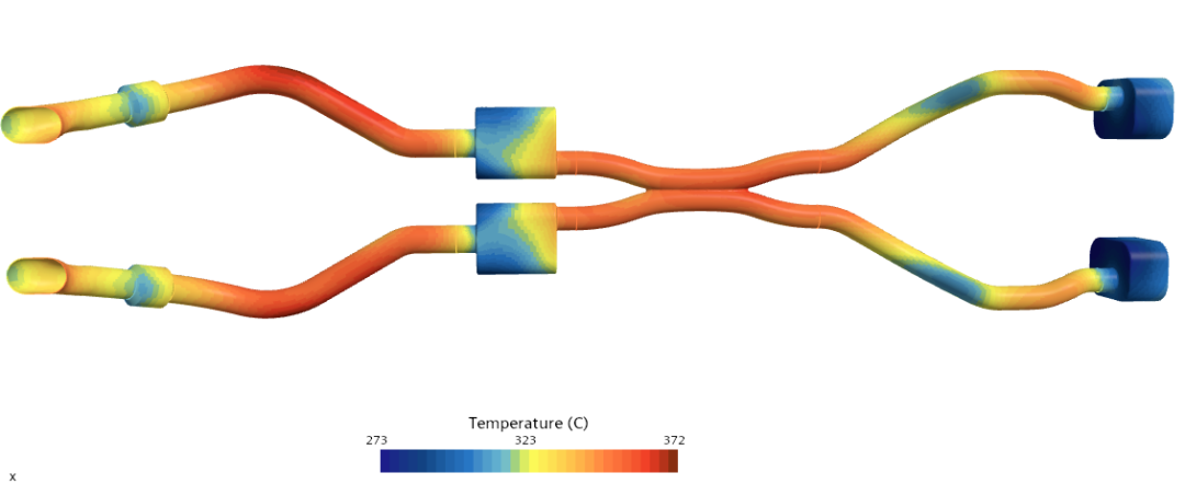
如果保持运行,模拟将一直持续到完成 500 次迭代。完成后,温度分布如下所示:
模拟运行完成后,保存它。