首页/文章/ 详情

三大疲劳校核方法

56分钟前浏览3

钢结构焊接疲劳评估,一文读懂名义应力、热点应力和有效缺口应力法,三大疲劳校核方法。

在钢结构工程中,疲劳失效是焊接结构最常见的破坏形式之一。

桥梁、海洋平台、起重机、轨道交通装备,长期承受往复交变载荷,焊缝位置极易萌生疲劳裂纹,威胁整体结构安全。

按照欧洲规范 EN 1993‑1‑9(Eurocode3),工程上有三套独立、不可混用的疲劳评估体系:名义应力法、热点应力法、有效缺口应力法。

三者由浅入深,核心差异在于应力定义、计算精度、建模难度各不相同。

选对方法,是做好疲劳校核的第一步。
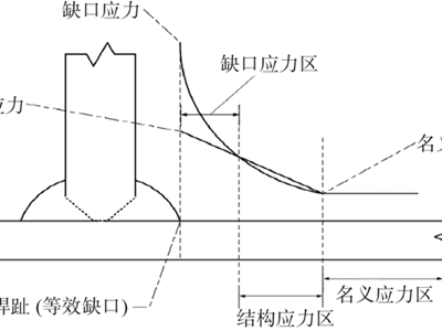
上图为焊接接头区域,名义应力、热点应力、缺口应力的应力分布对比示意图

一、工程最常用的基础校核手段名义应力法

名义应力法是 Eurocode3 的主体方法,也是目前通用钢结构设计里应用最广、历史最悠久的疲劳校核方法。

核心原理:

取远离焊缝应力集中区的宏观截面应力,通过材料力学或者整体有限元得到截面名义拉、剪应力;再根据接头构造细节分类,匹配对应的 S‑N 曲线,结合 Miner 累积损伤理论完成疲劳验算。

关键规则:

1.基于线弹性计算截面名义应力;角焊缝、部分熔透焊缝采用焊喉应力;螺栓拉杆按对应有效面积计算应力;

2.规范内置 12 套构造细节分类表格,覆盖轧制母材、螺栓连接、各类焊接接头、管节点、正交异性桥面板、起重机轨道梁等;

3.板厚大于基准厚度时,引入厚度修正系数对抗疲劳抗力进行折减;退火构件受压循环需要对压应力做折算处理。

优点:

方法成熟简单,建模成本低,规范配套完整,大量标准接头都有现成的 FAT 细节分类,常规项目上手快。

局限:

1.高度依赖接头细节分类,新型、非标复杂接头找不到匹配 S‑N 曲线;

2.不直接考虑焊缝局部缺口应力集中;

3.复杂结构中,有时很难清晰界定 “名义应力” 的提取位置。

适用场景:

建筑钢结构、通用机械,接头形式标准、构造简单的常规焊接结构。

二、有限元主流聚焦焊趾开裂热点应力法

随着有限元仿真普及,大量船舶、海洋、桥梁项目采用该方法。

核心原理:

热点应力仅统计宏观几何不连续带来的应力集中,剔除焊缝焊趾本身缺口带来的局部非线性应力峰值;通过有限元特定位置的应力外推得到焊趾热点应力,再调用热点专用 S‑N 曲线开展评估。
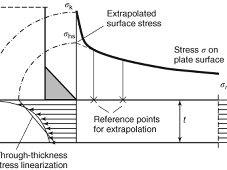
热点应力采用距离焊趾特定参考点做线性外推获取,避开焊缝缺口奇异应力区。

关键规则:

1.仅用于焊趾开裂失效,无法评估焊根破坏;分为板厚梯度、薄板边缘、空心管桁架三类热点;

2.有限元建模需要遵守 EN 1993‑1‑14 建模要求,网格质量、外推位置直接影响结果精度;

3.平板、圆管节点分别采用不同板厚修正系数,配套专用 B.1/B.2 表格。

优点:

充分考虑板厚突变、附件连接等宏观几何带来的应力集中;相比名义应力法精度更高;对于很多复杂板架、管状节点,不需要再费力匹配繁多的接头分类。

局限:

1.不能评估焊缝内部焊根起裂的疲劳问题;

2.计算结果对网格尺寸、单元类型、外推方案比较敏感;

3.需要局部精细化有限元建模,工作量高于名义应力法。

适用场景:

海洋平台、船舶、桥梁桁架,裂纹起始位置明确为焊趾的复杂焊接结构。

三、高精度兜底方案有效缺口应力法

有效缺口应力法是三种方法中精度最高,但建模代价最大的兜底方案,常规设计并不推荐优先使用。

核心原理

在焊趾、焊根位置引入1 mm 虚拟缺口圆角,模拟焊缝缺口效应;有限元直接计算虚拟缺口根部的有效缺口应力,同时覆盖焊趾、焊根两类裂纹起源,使用统一 S‑N 曲线开展评估。

关键规则:

1.适用板厚≥5 mm;对接焊趾取 30°、角接取 45°,统一缺口圆角 r=1 mm;

2.缺口根部网格需要极度细化,可采用主应力或者冯米塞斯等效应力幅计算疲劳损伤。

优点:

唯一一套可以同时评估焊趾、焊根两种起裂模式的标准方法;不依赖繁多的接头细节分类,复杂非标接头的兜底验算手段。

局限:

1.建模复杂,缺口区域网格要求极高,计算成本大,对工程师仿真能力要求高;

2.评估结果通常偏保守,容易造成设计过度加强;

3.适合关键危险节点局部校核,不适合全结构大规模批量计算。

适用场景:

轨道交通、高应力关键构件,接头形式复杂,焊趾焊根都存在开裂风险,需要精细评估的局部关键部位。

四、三大方法横向对比总表

特性

名义应力法

热点应力法

有效缺口应力法

应力定义

远离焊缝的截面宏观名义应力

焊趾外推得到的结构热点应力

1 mm 虚拟缺口根部的缺口应力

考虑因素

宏观结构,依靠接头细节分类

宏观几何不连续,排除焊缝局部缺口效应

宏观几何 + 焊缝缺口局部效应

可评估失效位置

依赖接头分类

仅焊趾

焊趾、焊根均可评估

S‑N 曲线特点

多条,按接头细节分类

热点专用曲线

单一通用 DC 曲线

建模复杂度

中等

精度水平

基础

中等

最高

主要短板

非标接头缺少对应分类,精度有限

无法评估焊根,网格敏感

计算量大,结果偏保守

五、精度与成本在工程上的权衡

1.常规标准化钢结构优先选名义应力法

接头形式在规范细节表里能找到,直接采用,效率最高,满足大部分建筑、通用钢结构设计。

2.复杂板架、管节点,焊趾为主要失效位置,选用热点应力法

海洋、船舶、桥梁,有限元分析为主,重点关注焊趾疲劳开裂。注意:一旦存在焊根开裂风险,热点应力法不能单独作为依据。

3.非标复杂关键接头,需要同时核查焊趾与焊根,采用有效缺口应力法做局部兜底校核

不作为整体批量验算手段,多用于关键危险节点复核,同时要留意结果偏保守带来的设计冗余问题。

三套评估体系相互独立,应力定义和 S‑N 曲线必须严格匹配,严禁交叉混用,否则疲劳损伤计算结果完全失效。

名义应力法求快,热点应力法求准,有效缺口应力法求全。

没有绝对最好的方法,只有最适配项目工况、接头形式、仿真能力的选择。理解三者的应力物理含义,分清适用边界,才能真正把钢结构疲劳校核落到实处。

参考标准:EN 1993‑1‑9 Eurocode3 钢结构疲劳规范、IIW 国际焊接学会疲劳设计推荐。
来源:智慧强学斋
疲劳非线性通用船舶轨道交通建筑海洋裂纹理论材料螺栓
著作权归作者所有,欢迎分享,未经许可,不得转载
首次发布时间:2026-09-15
最近编辑:56分钟前
强学斋
硕士 签名征集中
获赞 19粉丝 68文章 163课程 0
点赞
收藏
作者推荐

大家一起学标准之IEC61400-1(20)

点击听全文,今天大家继续一起学IEC61400-1。7.6.1.3 Partial safety factor for consequence of failure and component classesA consequence of failure factor, γn, is introduced to distinguish between:a) component class 1: used for "fail-safe" structural components whose failure does not result in the failure of a major part of a wind turbine, for example replaceable bearings with monitoring;b) component class 2: used for "safe-life" structural components whose failures may lead to the failure of a major part of a wind turbine;c) component class 3: used for "safe-life" mechanical components that link actuators and brakes to main structural components for the purpose of implementing non-redundant wind turbine protection functions. Regarding blocking devices, see 7.4.9.Partial safety factors for consequences of failure:·component class 1: γn = 0.9;·component class 2: γn= 1.0;·component class 3: γn= 1.2.The consequences of failure factor shall be included in the test load when performing tests such as, for example, full scale blade testing.Other values of γn apply for critical deflection an alysis, see 7.6.5.7.6.1.4 Application of recognized material codesWhen determining the structural integrity of elements of a wind turbine, national or international design codes for the relevant material may be employed. Special care shall be taken when partial safety factors from national or international design codes are used together with partial safety factors from this document. It shall be ensured that the resulting safety level is not less than the intended safety level in this document.Different codes subdivide the partial safety factors for resistance,γM, into several material factors accounting for separate types of uncertainty, for example inherent variability of material strength, extent of production control or production method. If the code gives partial safety factors or uses reduction factors on the characteristic values to account for other uncertainties, these shall also be taken into account.Individual codes may choose different factorizations of partial safety factors on the load and the material parts of the design verification. The division of factors intended here is the one defined in ISO 2394. If the division of factors in the code of choice deviates from that of ISO 2394, the necessary adjustments in the code of choice shall be taken into account in verifications according to this document.7.6.2 Ultimate strength an alysis7.6.2.1 GeneralThe limit state function can be separated into load and resistance functions S and R so that the condition becomesγn S(Fd)≤Rd {31}The function S for ultimate strength an alysis is usually defined as the highest value of the structural response, hence S(Fd) = Fd. The equation then becomesγnγFk ≤Rk/γM {32}Note that γn is a consequence of failure factor and shall not be treated as a safety factor on materials.For each wind turbine component assessed and for each load case in Table 2 where ultimate strength a nalysis is appropriate, the limit state condition in Equation (32) shall be verified for the most critical limit state, identified on the basis of having the least margin.7.6.2.2 Partial safety factors for loadsFor DLC 1.1, a characteristic value of load shall be determined by a statistical an alysis of the extreme loading that occurs for normal design situations and shall correspond to one of the following alternatives.a) The characteristic value is obtained as the largest (or smallest) among the average values of the 10 min extremes determined for each wind speed in the given range, multiplied by 1,35. This method can only be applied for the calculation of the blade root in-plane moment and out-of-plane moment and tip deflection.b) The characteristic value is obtained as the largest (or smallest) among the 99th percentile (or 1st percentile in the case of minima) values of the 10 min extremes determined for each wind speed in the given range, multiplied by 1,2.c) The characteristic value is obtained as the value corresponding to a 50 year return period, based on load extrapolation methods, considering the wind speed distribution given in 6.3.2.1 and the normal turbulence model in 6.3.2.3. Guidance about load extrapolation is given in Annex G.The design load will be then obtained by multiplying the characteristic loads according to any of these alternatives by the partial safety factor for DLC 1.1 defined in Table 3.For all three alternatives above, data used in the statistical an alysis shall be extracted from time series of turbine simulations of at least 10 minutes in length over the operating range of the turbine for DLC 1.1. A minimum of 15 simulations is required for each wind speed from Vr-2m/s to cut-out, and six simulations are required for each wind speed below Vr-2m/s. When extracting data, the designer shall consider the effect of independence between peaks on the statistical an alysis and minimize dependence when possible. For guidance on dependency checks, see Annex G.For load cases with specified deterministic wind field events, the characteristic value of the load shall be the worst case computed transient value. If more simulations are performed at a given wind speed, representing the rotor azimuth, the characteristic value for the load case is taken as the average value of the worst case computed transient values at each azimuth. Guidance for the derivation of the contemporaneous load can be found in Annex I. When turbulent inflow is used, the mean value among the worst case computed loads for different 10 min stochastic realizations shall be taken, except for DLC 2.1, 2.2 and 5.1, where the characteristic value of the load shall be the mean value of the largest half of the maximum loads.Partial safety factors for loads shall be at least the values specified in Table 3.The approach in 7.6.1.2, where the partial safety factor for loads is applied to the load response, assumes that a proper representation of the dynamic response is of prime concern. Where a proper representation of non-linear material behaviour or geometrical non-linearities (such as, for example, foundations) or both are of primary concern, the design load response Sd shall be obtained from a structural an alysis for the combination of the design loads Fd, where the design load is obtained by multiplication of the characteristic loads Fk by the specified partial load factor γf for favourable and unfavourable loads:Fd=γfFk {33}The load responses in the tower at the interface (shear forces and bending moments) factored with γf from Table 3 shall be applied as boundary conditions.Table 3 – Partial safety factors for loads γfUse of the partial safety factors for loads for normal and abnormal design situations specified in Table 3 requires that the load calculation model is validated by load measurements. These measurements shall be made on a wind turbine that is similar to the wind turbine design under consideration with respect to aerodynamics, control and dynamic response.二、精准工程译文(IEC 风电标准术语)7.6.1.3 失效后果分项安全系数与构件类别引入失效后果系数\(\boldsymbol{\gamma_\mathrm{n}}\),用于区分三类构件:a) 1 类构件:故障安全型构件;构件失效不会造成机组主体失效,例如具备监测、可更换轴承;b) 2 类构件:安全寿命型结构构件;构件失效可能引发机组主体失效;c) 3 类构件:安全寿命型机械构件;用于连接执行机构、制动器与主结构,实现无冗余机组保护功能。锁止装置相关要求见 7.4.9。失效后果分项安全系数取值:·1 类构件: γn = 0.9;·2 类构件: γn = 1.0;·3 类构件: γn = 1.2。开展全尺寸叶片等试验时,试验荷载中必须计入失效后果系数。临界变形分析采用另行规定的 γn取值,见 7.6.5。7.6.1.4 公认材料规范的应用确定机组构件结构完整性时,可采用对应材料的国家或国际设计规范。当外部规范分项安全系数与本标准系数联合使用时需格外谨慎,必须保证最终安全水平不低于本标准规定目标。不同规范会将抗力分项系数\(\gamma_\mathrm{M}\)进一步拆分为多个材料分项系数,分别考虑材料强度固有离散性、生产管控水平、制造工艺等不确定性。若外部规范采用分项系数或特征值折减系数考虑其他不确定因素,均应一并纳入计算。各类规范对荷载侧、材料侧分项系数的拆分方式存在差异。本标准系数拆分原则与 ISO 2394 一致;若选用规范的拆分方式与 ISO 2394 不同,按照本标准开展校核时必须进行相应修正。7.6.2 极限强度分析7.6.2.1 总则极限状态函数可拆分为荷载函数S与抗力函数R,极限状态判定条件:γn S(Fd)≤Rd {31}极限强度分析中函数S一般取结构响应最大值,即S(Fd) = Fd,公式简化为:γnγFk ≤Rk/γM {32}注意:γn为失效后果系数,不得视作材料安全系数。针对每一个待评估构件,以及表 2 中适用极限强度分析的各个荷载工况,均需按照式 (32) 校核最临界极限状态(裕度最小工况)。7.6.2.2 荷载分项安全系数对于 DLC 1.1 工况,应通过正常设计工况极值荷载统计确定荷载特征值,可选用以下三种方法之一:a) 取规定风速区间内各风速 10 分钟极值平均值的最大 / 最小值,再乘以 1.35;该方法仅限用于叶根面内弯矩、面外弯矩以及叶尖挠度计算。b) 取规定风速区间内各风速 10 分钟极值 99% 分位数(最小值采用 1% 分位数)的最大 / 最小值,再乘以 1.2。c) 采用荷载外推方法得到 50 年重现期对应荷载;风速分布依据 6.3.2.1、正常湍流模型依据 6.3.2.3,荷载外推指导见附录 G。采用上述任意一种方法得到特征荷载后,乘以表 3 规定的 DLC 1.1 荷载分项系数得到设计荷载。上述三种方法统计所用数据,均取自机组至少 10 分钟时长仿真时程。DLC 1.1 工况下:额定风速减 2 m/s 至切出风速区间,每个风速至少完成 15 次仿真;低于额定风速减 2 m/s 的风速,每个风速至少 6 次仿真。提取数据时需评估峰值之间的相关性影响,尽可能降低数据相关性;相关性校核方法参见附录 G。对于给定确定性风场事件的工况,荷载特征值取最不利瞬态计算结果;同一风速下开展多组不同风轮方位仿真时,取各方位最不利瞬态结果平均值。同步荷载获取方法参见附录 I。采用湍流入流时,取多组 10 分钟随机仿真最不利荷载的平均值;DLC 2.1、2.2、5.1 除外,这三类工况取全部最大值中较大一半数值的平均值作为荷载特征值。荷载分项安全系数不得低于表 3 规定数值。7.6.1.2 中将分项系数施加于荷载响应的思路,适用于重点关注结构动态响应的场景。若分析核心为材料非线性、几何非线性(如基础)或两者共存,则先将特征荷载Fk乘以荷载分项系数 γf得到设计荷载 γd,再通过结构分析求解设计荷载响应Sd:Fd=γfFk {33}塔筒界面位置经过表 3γf放大后的荷载响应(剪力、弯矩)应作为边界条件施加。表 3 荷载分项安全系数γf采用表 3 正常 / 异常工况荷载分项系数时,荷载计算模型必须通过实测验证;试验机组在气动特性、控制系统、动态响应方面应与目标设计机组相近。简单总结本节按照失效后果将构件划分为三类并给出对应的γn系数,同时明确外部材料规范协同使用要求。极限强度校核给出统一判定公式,规定 DLC1.1 等工况荷载特征值三种统计方法、仿真数量要求与各类工况荷载分项安全系数取值规则,并区分线性动态、非线性分析两种不同系数施加路径。今天就学到这里,明天我们继续学习,每天十分钟大家一起学标准。来源:智慧强学斋

未登录
还没有评论
课程
培训
服务
行家
VIP会员 学习计划 福利任务
下载APP
联系我们
帮助与反馈