中英文混合的段落相似度查询---Bonded Particle Model (BPM)

1 引言
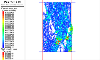
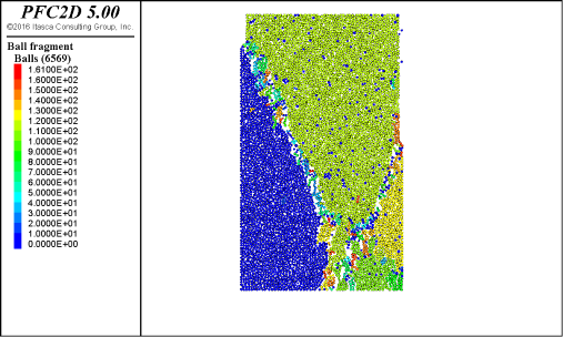
句子或段落的相似度查询是基于语言预训练的model实现的。即使对于同一种语言, 不同的model得出的结果也不完全相同。而对于双语或多语言混合的查询,不同的model 得出的结果就更不相同。在《使用Transformers确定句子之间的相似度》中,我们只使用了全英语的预训练model, 尽管我们大部分处理的语言是英语,但有时也要处理一些中文,因此引入了一个新的多语言预训练model。本文简要描述了如何使用这个model实现中英文混合查询。采用的数据集是Bonded Particle Model (BPM)---粘结颗粒模型,一种在PFC中使用的构造原岩的模型,参看《离散断裂网络(DFN)[P4]: 创建一个合成岩体SRM》和《离散断裂网络(DFN)[P3]: fracture contact-model》。
2 中英文混合查询的方法 论
现在,我们有两个预训练的model,一个是纯英语的model, 另一个是多语言的model,为了能精确捕捉更多的中英文信息,我们设计在同一次运行中同时使用这两个model, 于是把这两个model组成一个list。
models = [SentenceTransformer('roberta-large-nli-stsb-mean-tokens'), \SentenceTransformer('distiluse-base-multilingual-cased')]
然后对这两个model进行循环:
for each_model in models:do something ;进行计算
3 方法测试
3.1 测试1
在这个测试里,我们要查询的句子是“岩体强度参数和 Bonded Particle Model (BPM)”。运行代码后得出的结果如下:
Model-1:
Numerical Modeling and the Bonded Particle Model 数值模拟和粘结颗粒模型
合成岩体SRM是由Bonded Particle Model 和 Smooth-Joints 组成的。
The Theory of Bonded Particle Modeling 粘结颗粒模拟的理论
Assembly and Calibration of the Bonded Particle Models 粘结颗粒模型的组装和标定
节理岩体的合成岩体模型 岩石力学:满足社会的挑战和要求,第1卷和第2期描述了预测节理岩体行为的新方法,其中涉及“合成岩体”(SRM)样本的构建和测试。SRM样本是三维的,可将岩石模拟为粘结球体(完整岩石)的组合,并具有嵌入式离散的圆盘状缺陷(接头)网络。该技术汇集了两种公认的方法:PFC3D中的键合粒子模型(BPM)(Potyondy&Cundall 2004)和离散断裂网络(DFN)模拟。该方法还采用了新的滑动节理模型,可以快速模拟包含数千个节理的大岩石体积。SRM的输入来自标准岩体表征方法,而输出则采用岩体性质的形式,可用于经验,数值或分析方法中。特别令人感兴趣的是获得岩体脆性预测的能力。这被认为是向前迈出的重要一步,因为还没有建立量化此特性的方法。SRM技术的验证已经通过在一个案例研究的矿山洞穴矿井中通过比较预测的和推断的压裂来实现(Reyes-Montes等,2007)。
Model-2:
Bonded Particle Model for Jointed Rock Mass
A Bonded Particle Model Simulation of Shear Strength and Asperity Degradation for Rough Rock Fractures
The Bonded Particle Model (BPM) is a discontinuum approach to modeling complex scenarios. It turns out, such a discontinuum-based approach for modeling rock deformation is appealing since it eliminates the need for complex constitute failure relations required for continuum approaches (Hazzard et al., 2000). In this approach, stress/strain, failure and the dynamics of particle displacements is free to propagate naturally. The BPM is a speci c implementation of the more general modeling technique known as the Discrete Element Method (DEM). The DEM employs rigid or deformable body mechanics to a discrete system of blocks, particles, or bodies where the discrete particles interact with each other through contacts. The behavior of the blocks at the contacts can be very general. Once the interaction of contacts is assessed for all particles in the system, the updated positions of the particles are found by integration of the equations of motion over the time-step or cycling parameter (Ling, 2003). The BPM is a particular example of the DEM where the discrete particles are now rigid spheres and the contact interaction between particles is elasticity described by Hooke's Law.
Intact Rock PFC Bonded Particle Model (Potyondy and Cundall, 2004)
The bonded particle model (BPM) was presented by Potyondy & Cundall (2004). The BPM simulates an intact rock as a packing of non uniform circular or spherical rigid particles that are connected together at their contact points with parallel bonds. The micro mechanical properties of the rigid particles are shear and normal stiffness and coefficient of friction. The micro-properties of the parallel bonds are normal and shear stiffness, tensile and shear strength and parallel bond radius multiplier. A bonded particle model can represent a homogeneous rock, or it can be divided into a number of discrete regions or blocks by fractures. The properties of particles and bonds along the fracture planes are usually different than those that exist in the solid part of the model.
结果发现两个model给出的结果完全不一样。另外需注意,为了演示起见,测试中的部分中文由百度翻译自动生成,因此有些中文句子的表达显得有点儿stupid。
3.2 测试2
在这个测试里,我们要查询的句子是“合成岩体SRM是由 BPM和smooth joint组成的”。运行代码后的结果如下:
Model-1:
合成岩体SRM是由Bonded Particle Model 和 Smooth-Joints 组成的。
不同载荷速率下的岩石的机械性能对动态载荷条件下的内失效机制有积极的影响。在花岗岩标本上使用颗粒流代码(PFC=(2D)中的粘结颗粒模型(BPM)对花岗岩标本进行单轴压缩和巴西测试的数值模拟。为了量化压缩强度、拉伸强度、失效模式、应变能量速率和声学发射率相关行为,选择从 0.001 到 0.500 m/s 的四种不同的装载速率。单轴压缩强度(UCS)及其相应的应变,以及拉伸强度及其相应的应变随装载速率非线性增加。故障模式和损坏程度也受装载速率的影响。结果发现,压缩载荷下的试样具有单倾斜部分,载荷率较低,而具有较高装载速率的多个强制节形。此外,裂纹数和高水平应变率分布表明,失效区面积和损伤程度随装载率的增加而增加。在巴西的测试中,随着装载速率的增加,故障模式从一个主裂纹变为几个主要裂纹。裂缝延伸到圆标本的边缘,装载速率会加剧损伤程度。此外,两次测试中试样的声学发射计数和应变能量速率以非线性形式增加,载荷率也不断提高。
使用粘结粒子模型 (BPM)和类似的方案,可以模拟 PFC 和其他 DEM 代码中完整岩石的力学行为。以这些模型为基础,试图在装配体内通过选择性脱粘来合成连接岩体[3,4]。如 [4] 中所述,该方法的潜在力量是,丰富的紧急材料响应可以来自岩石和关节相对简单的粒子接触定律,而不是更复杂的用户指定的组织模型。然而,由于使用选择性脱粘的粒子触点进行关节表示,导致关节过于粗糙和"凹凸",以及计算限制,使分析限制在二维中相对较少的关节。
节理岩体的合成岩体模型 岩石力学:满足社会的挑战和要求,第1卷和第2期描述了预测节理岩体行为的新方法,其中涉及“合成岩体”(SRM)样本的构建和测试。SRM样本是三维的,可将岩石模拟为粘结球体(完整岩石)的组合,并具有嵌入式离散的圆盘状缺陷(接头)网络。该技术汇集了两种公认的方法:PFC3D中的键合粒子模型(BPM)(Potyondy&Cundall 2004)和离散断裂网络(DFN)模拟。该方法还采用了新的滑动节理模型,可以快速模拟包含数千个节理的大岩石体积。SRM的输入来自标准岩体表征方法,而输出则采用岩体性质的形式,可用于经验,数值或分析方法中。特别令人感兴趣的是获得岩体脆性预测的能力。这被认为是向前迈出的重要一步,因为还没有建立量化此特性的方法。SRM技术的验证已经通过在一个案例研究的矿山洞穴矿井中通过比较预测的和推断的压裂来实现(Reyes-Montes等,2007)。
粘合颗粒模型 (BPM) 是一种不连续的方法来建模复杂方案。事实证明,这种基于连续的岩石变形建模方法很有吸引力,因为它消除了连续方法所需的复杂构成失效关系(Hazzard等人,2000年)。在这种方法中,应力/应变、失效和粒子位移的动态可以自由自然传播。BPM 是称为离散元素方法 (DEM) 的更通用建模技术的 speci 实现。DEM 使用刚性或可变形的体力学到离散的块、粒子或实体的离散系统,其中离散粒子通过触点相互作用。触点上的块的行为可能非常一般。一旦对系统中所有粒子的触点相互作用进行评估,粒子的更新位置就会通过在时间步长或循环参数中整合运动方程来找到粒子的更新位置(Ling,2003年)。BPM 是 DEM 的一个特定示例,其中离散粒子现在是刚性球体,粒子之间的接触相互作用是胡克定律描述的弹性。
Model-2:
合成岩体SRM是由Bonded Particle Model 和 Smooth-Joints 组成的。
Jointed rock masses are formed of intact rock and joints. Therefore, proper characterization of rock mass behavior has to consider the combined behavior of the intact rock blocks and that of the joints. This thesis presents the theoretical background of the Synthetic Rock Mass (SRM) modeling technique along with example applications. The SRM technique is a new approach for simulating the mechanical behavior of jointed rock masses. The technique uses the Bonded Particle Model (BPM) for rock to represent intact material and the Smooth-Joint Contact Model (SJM) to represent the in situ joint network. In this manner, the macroscopic behaviour of an SRM sample depends on both the creation of new fractures through intact material, and slip/opening of pre-existing joints. SRM samples containing thousands of non-persistent joints can be submitted to standard laboratory tests (UCS, triaxial loading, and direct tension tests) or tested under a non-trivial stress path representative of the stresses induced during the engineering activity under study. Output from the SRM methodology includes pre-peak properties (modulus, damage threshold, peak strength) and post-peak properties (brittleness, dilation angle, residual strength, fragmentation). Of particular interest is the ability to obtain predictions of rock mass scale effects, anisotropy and brittleness; properties that cannot be obtained using empirical methods of property estimation. Additionally, the nature of yielding and fracturing can be studied as the rock mass fails. This information can improve our understanding of rock mass failure mechanisms.
The Synthetic Rock Mass (SRM) model was presented as a hybrid distinct element model/ fracture system model. To set up a synthetic rock mass model, the PFC is used to construct a solid rock as a bonded particle model. The bonded particle model simulates the intact rock by representing it as an assemblage of bonded circular or spherical particles. The bonded particle model is calibrated to establish the mechanical properties of intact rock measured in the laboratory. These properties include elastic modulus, Poisson's ratio, UCS and tensile strength. A network of fractures simulated by a fracture system model based on the fracture mappings in the field are then inserted in the bonded particle model. The smooth joint model is assigned to the particle contacts along the fractures. This allows associated particles to slide through each other along the fracture plane rather than pass over each other.
The SRM method is based on the generation and testing of three dimensional numerical (synthetic) rock mass samples. This new method brings together two well-established techniques: the Bonded Particle Model for rock, developed by Potyondy and Cundall (2004) for the simulation of intact rock deformation and brittle fracture, and Discrete Fracture Network modelling for the representation of the rock mass in situ joint fabric (Figure 5). Each individual joint is represented explicitly within the SRM sample, making use of the recently developed Smooth-Joint contact Model (SJM) (Mas Ivars et al. 2008b; Potyondy et al. 2010). This new technique of joint representation in PFC3D has made it possible to extend the approach of Park et al. (2004) to volumes of rock at the scale of 10 to 100 m, containing thousands of non-persistent joints. Each SRM component is discussed separately in more detail below.
In this study, a 3D Synthetic Rock Mass (SRM) method is used to characterize the effect of joint sets on hard rock pillar strength and deformation. The SRM is an integrated simulation technique involving a Bonded Particle Model (BPM) and a Discrete Fracture Network (DFN). Based on the numerical results of a joint-free1 model, some important modelling configuration is discussed for rock pillars, including the loading method and boundary condition. A systematic sensitivity analysis on the effect of joint set orientation and size is conducted. A U-shape relationship is simulated for the pillar peak strength with change in joint set orientation. Increased joint set size results in a reduction in the pillar peak strength. For most jointed pillar simulations, the post-peak in the axial stress vs axial strain curve shows two characteristic stages. The first stage corresponds to a brittle/strain-softening behaviour, followed by a second ductile residual stage. The effect of joint sets on the pillar deformation modulus is similar to the observed effect on the pillar peak strength. In contrast, the effect on the lateral stiffness ratio is reversed, with an inverted U-shape relationship. The pillar crack initiation stress (σci) and crack damage stress (σcd) thresholds are characterized for the jointed pillar models, where the ratio of the pillar crack initiation stress/peak strength is between 30%-45%, and the ratio of the pillar crack damage stress/peak strength is between 75%-98%. The simulated pillar failures are plotted as 3D views and as 2D thin layers for selected pillar models. The effect of joint set persistence is finally investigated, and in comparison with the variation of the mechanical pillar property induced by the joint set size, the property variation is less significant when the joint set persistence is changed. Due to constant joint set intensity, the effect of the joint set persistence is reduced compared with the effect of the joint set size.
结果显示两个model只有“合成岩体SRM是由Bonded Particle Model 和 Smooth-Joints 组成的”这一句相同,其余都不同。多语言model给出的结果更多是中文,纯英语model给出的结果更多是英文。
5 结束语
为了能够进行中英文混合查询,精确捕捉所需信息,本文试验了同时使用了纯英文和多语言的预训练model,结果显示这种联合的方法能够最大程度地得到我们需要的东西。将来我们逐步训练自己专业领域---岩土工程的大数据集,合并到目前公共领域的预训练集,使得学习性能得到进一步提升。
本文相似文档