PFC柔性三轴
本文摘要(由AI生成):
本文展示了一个柔性三轴试验的模拟结果,通过施加力并观察矢量图,可以清晰地看到剪胀现象。文章对模拟过程进行了简要描述,并重点展示了不同孔隙率下的模拟结果。通过对比不同孔隙率的模型图和位移图,发现松砂表现出剪缩现象,而密砂则表现出剪胀现象。此外,文章还提到了最低孔隙率的概念,并指出超过这个孔隙率将使结果变得不再合理。最后,通过动画展示了不同孔隙率下的模拟效果,为读者提供了更直观的理解。
0 前言
2021快年底了,这应该是今年最后一篇文章。很开心自己录制得入门课程在全平台播放量约20w。今年最后也分享一个离散元中得一个关键技术点-柔性三轴的实现。
这部分内容一年多以前就写好了,只是一直反映有bug,所以后面就下架了。在咸鱼里面也看到了很多盗版贩卖我的代码,导致很多人有了问题不知道怎么解决。这篇文章简单介绍一下柔性三轴的实现框架。
1 成样
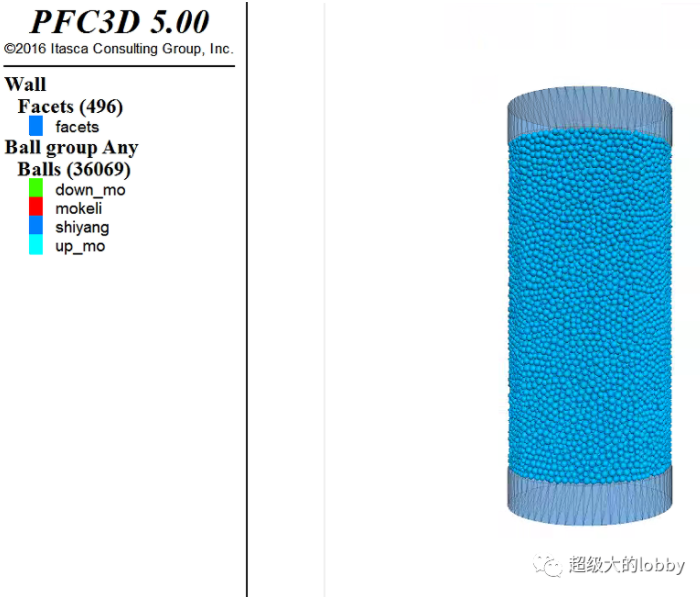
这部分内容有个特别注意的地方是,我目前使用的5.0版本,圆形或者圆柱形墙体在计算的时候经常出现大颗粒在两个小面片间不停波动的情况,导致平衡不了。这应该是PFC的一个计算bug了。
这里提供的一个解决办法是将圆柱形墙体的分辨率(resolution )提高,这样颗粒不会比面片大很多,于是就比较容易平衡下来了。
newdef chicun_parsample_rad=0.2sample_hight=sample_rad*4keli_rdmin=0.006keli_rdmax=0.009end@chicun_pardomain extent [-sample_rad*2] [sample_rad*2] [-sample_rad*2] [sample_rad*2] [-sample_hight*1.5] [sample_hight*1.5][n=1.4]set random 10001wall generate cylinder base 0 0 [-sample_hight*0.5*n] axis 0 0 1 ...height [sample_hight*n] radius [sample_rad] resolution 0.5 cap false falsewall generate plane position 0 0 [sample_hight*0.5] dip 0 ddir 0wall generate plane position 0 0 [-sample_hight*0.5] dip 0 ddir 0ball distribute group shiyang radius [keli_rdmin] [keli_rdmax] porosity 0.32 ...range cylinder end1 0 0 [sample_hight*0.5-keli_rdmin] ...end2 0 0 [-sample_hight*0.5 keli_rdmin] radius [sample_rad-keli_rdmin]cmat default model linear method deform emod 100e6 kratio 1.5ball attribute density 2.7e3 damp 0.7cycle 2000 calm 50solvesave sample
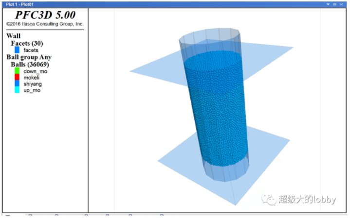
成好的样为:
2 预压
这里模拟的是砂土,给一个10kpa的预压用于调整内应力。关于环状伺服的原理这里不做太多讲解。
restore sampleball property fric 0.5def wp_wallwp_up=wall.find(2)wp_down=wall.find(3)wp_rr=wall.find(1)loop foreach vt wall.vertexlist(wp_rr)vert_in_ce=vtendloopend@wp_wall[tzz=-1e4][trr=-1e4][sevro_fac=0.5][do_zservo=true][do_rservo=true][sevro_freq=100][timestepNow=global.step-1]def servo_wallscomputer_wallStressif timestepNow<global.step thenget_gain(sevro_fac)timestepNow =sevro_freqendifif do_zservo=true thenz_vel=gz*(wszz-tzz)wall.vel.z(wp_up)=-z_velwall.vel.z(wp_down)=z_velendifif do_rservo=true thenr_vel_mag=(-1)*gr*(wsrr-tzz)loop foreach vt wall.vertexlist(wp_rr)mag=math.sqrt(wall.vertex.pos.x(vt)^2 wall.vertex.pos.y(vt)^2)fang_normal_x=wall.vertex.pos.x(vt)/magfang_normal_y=wall.vertex.pos.y(vt)/magr_vel=vector(fang_normal_x,fang_normal_y,0)*r_vel_magwall.vertex.vel(vt)=r_velendloopendifenddef computer_chicunx_pos=wall.vertex.pos.x(vert_in_ce)y_pos=wall.vertex.pos.y(vert_in_ce)wlr=math.sqrt(x_pos^2 y_pos^2)wlz=wall.pos.z(wp_up)-wall.pos.z(wp_down)enddef computer_wallStresscomputer_chicunding_yuanmianji=math.pi*wlr^2wszz=(wall.force.contact.z(wp_down)-wall.force.contact.z(wp_up))*0.5/ding_yuanmianjice_mianji=2*math.pi*wlr*wlzwsrr=0loop foreach ft wall.facetlist(wp_rr)ft_fangxiang=wall.facet.normal(ft)loop foreach ct wall.facet.contactmap(ft)force_in_facet=contact.force.global(ct)wsrr =-(math.dot(force_in_facet,ft_fangxiang))/ce_mianjiendloopendloopenddef get_gain(fac)gz=0gr=0zonggangZ=0zonggangR=0loop foreach ct wall.contactmap(wp_up)zonggangZ =contact.prop(ct,"kn")endlooploop foreach ct wall.contactmap(wp_down)zonggangZ =contact.prop(ct,"kn")endlooploop foreach ct wall.contactmap(wp_rr)zonggangR =contact.prop(ct,"kn")endloopgz=fac*ding_yuanmianji/(zonggangZ*global.timestep)gr=fac*ce_mianji/(zonggangR*global.timestep)endset fish callback -1.0 @servo_wallshistory id 1 @wszzhistory id 2 @wsrrcycle 1solvesave yuya
3 围压
restore yuya[tzz=-3e5][trr=-3e5]cycle 1solvesave weiya
4 加柔性膜
这里尽量展开讲一下
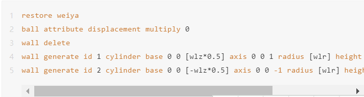
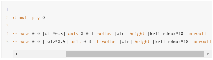
step-1: 第一件事情是将墙体都删除,然后生成上下的加载板
step-2: 之后是一个根据圆半径和颗粒数,计算紧密排列的环状分布颗粒的粒径。
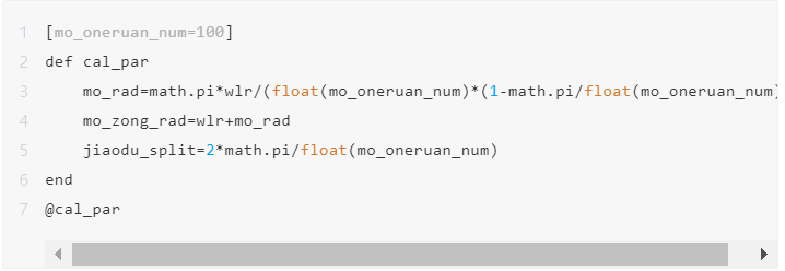
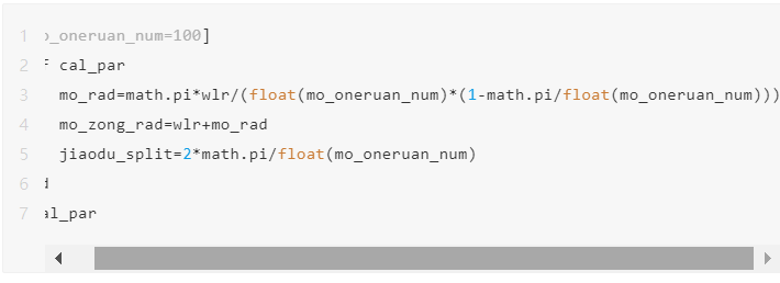
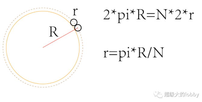
下面是这个计算的原理,利用圆环中心线的周长相等建立R和r的关系。代码中是一种更精细的做法,但是可以看到 pi/Num基本上就是0了,所以可有可无。mo_rad即为膜颗粒的半径,mo_zong_rad为圆环中心线的半径。
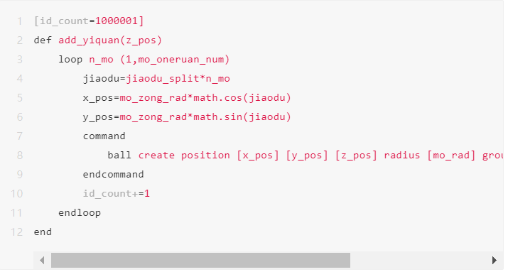
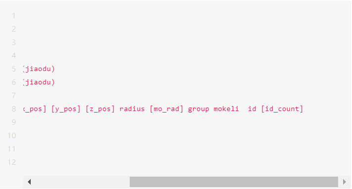
step-3:定义生成一圈膜颗粒的函数,这里比较简单,需要传入圆环分布的Z坐标,剩余的事情其实是二维的。
step-4:生成膜颗粒
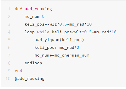
这里就是指定Z坐标,利用上面写好的生成一圈膜颗粒的函数进行循环生
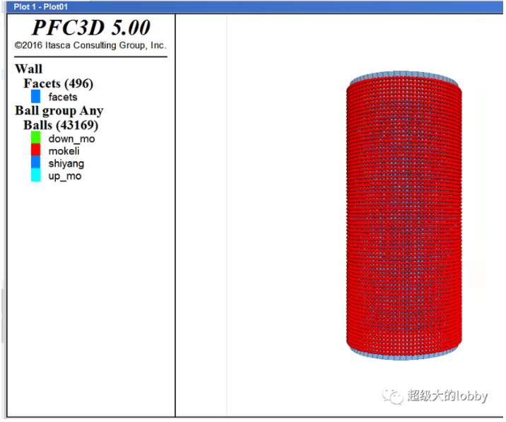
生成好的膜颗粒如图:
step-5:膜颗粒参数定义
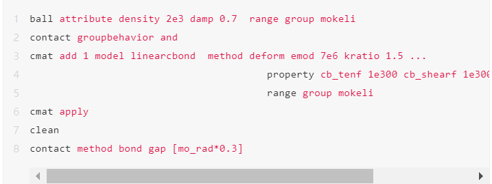
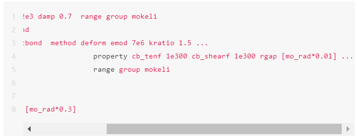
这里用的还是cb模型,模量取7Mpa。
step-6:膜颗粒加力
膜颗粒的力计算如图,这里和二维一样,用的是等效,将面积压力乘面积来计算集中力施加到颗粒上。
每个颗粒所代表的面积为黄色 区域,目前颗粒是规则排列的,所以是一个正方形。当颗粒发生变形后,黄色部分面积应为四个平行四边形拼起来的。这四个平行四边形的面积产生的力可以由cal_F_from_three_ball 这个函数来计算。由于是平行四边形,所以三个坐标就可以决定这个形状了。
两个向量形成的平行四边形面积为叉乘的膜,这个是高中知识了,这里也是利用这个原理来计算面积,乘力就是这个平行四边形施加在颗粒上的集中力了。
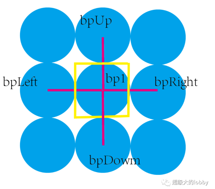
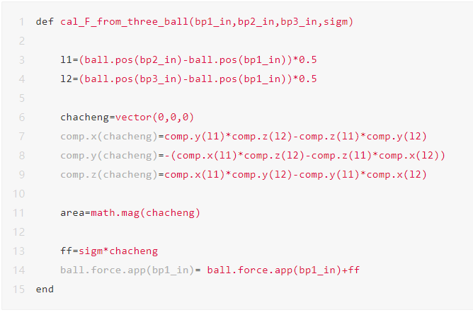
需要注意的是,这里用的是ID号去识别的左右上下的颗粒,而这样的话,对于每一圈的首个和最后一个颗粒应当是要区分一下的。这里使用的是整形除以整形与浮点型之间的区别来识别首端和尾端颗粒。
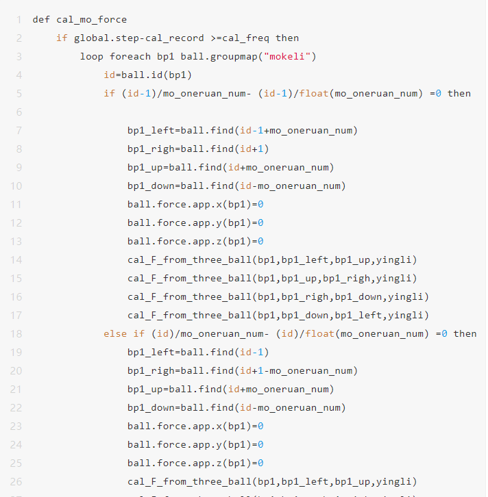
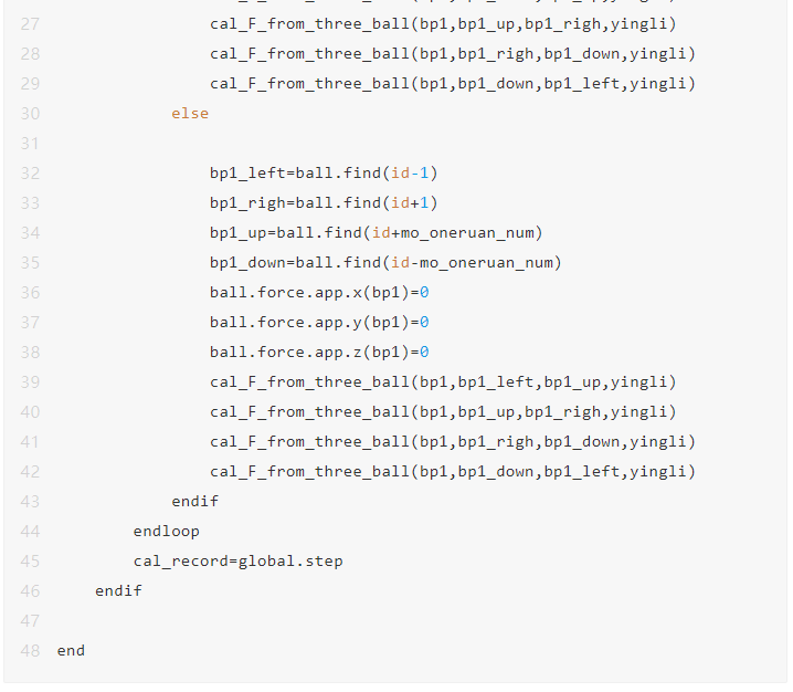
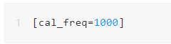
当然计算效率起见,我们设置了每1000步更新一次膜颗粒的力。
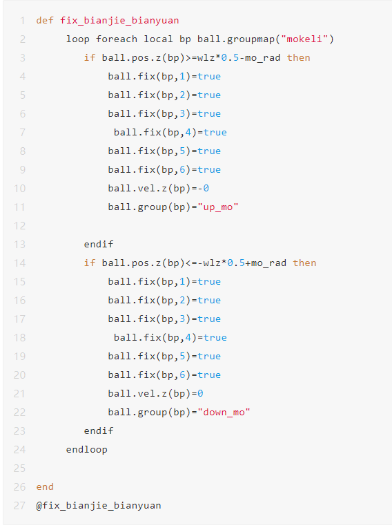
step-7:固定加载板上的颗粒
这里和二维一样,将膜绑定在加载板
step-8:指定上下加载板的伺服
def servo_wallshuxiangwlz=wall.pos.z(wp_up)-wall.pos.z(wp_down)-keli_rdmax*10if do_zservo=true thenz_vel=gz*(wszz-tzz)wall.vel.z(wp_up)=-z_velwall.vel.z(wp_down)=z_velloop foreach local bp_up ball.groupmap("up_mo")ball.vel.z(bp_up)=-z_velendlooploop foreach local bp_down ball.groupmap("down_mo")ball.vel.z(bp_down)=z_velendloopendifend
为了大家复 制方便,这里将柔性膜的所有代码放在一起
restore weiyaball attribute displacement multiply 0wall deletewall generate id 1 cylinder base 0 0 [wlz*0.5] axis 0 0 1 radius [wlr] height [keli_rdmax*10] onewallwall generate id 2 cylinder base 0 0 [-wlz*0.5] axis 0 0 -1 radius [wlr] height [keli_rdmax*10] onewall[mo_oneruan_num=100]def cal_parmo_rad=math.pi*wlr/(float(mo_oneruan_num)*(1-math.pi/float(mo_oneruan_num)))mo_zong_rad=wlr mo_radjiaodu_split=2*math.pi/float(mo_oneruan_num)end@cal_par[id_count=1000001]def add_yiquan(z_pos)loop n_mo (1,mo_oneruan_num)jiaodu=jiaodu_split*n_mox_pos=mo_zong_rad*math.cos(jiaodu)y_pos=mo_zong_rad*math.sin(jiaodu)commandball create position [x_pos] [y_pos] [z_pos] radius [mo_rad] group mokeli id [id_count]endcommandid_count =1endloopenddef add_rouxingmo_num=0keli_pos=-wlz*0.5-mo_rad*10loop while keli_pos<wlz*0.5 mo_rad*10add_yiquan(keli_pos)keli_pos =mo_rad*2mo_num =mo_oneruan_numendloopend@add_rouxingball attribute density 2e3 damp 0.7 range group mokelicontact groupbehavior andcmat add 1 model linearcbond method deform emod 7e6 kratio 1.5 ...property cb_tenf 1e300 cb_shearf 1e300 rgap [mo_rad*0.01] ...range group mokelicmat applycleancontact method bond gap [mo_rad*0.3][yingli=math.abs(trr)][cal_freq=1000][cal_record=global.step-cal_freq]def cal_mo_forceif global.step-cal_record >=cal_freq thenloop foreach bp1 ball.groupmap("mokeli")id=ball.id(bp1)if (id-1)/mo_oneruan_num- (id-1)/float(mo_oneruan_num) =0 thenbp1_left=ball.find(id-1 mo_oneruan_num)bp1_righ=ball.find(id 1)bp1_up=ball.find(id mo_oneruan_num)bp1_down=ball.find(id-mo_oneruan_num)ball.force.app.x(bp1)=0ball.force.app.y(bp1)=0ball.force.app.z(bp1)=0cal_F_from_three_ball(bp1,bp1_left,bp1_up,yingli)cal_F_from_three_ball(bp1,bp1_up,bp1_righ,yingli)cal_F_from_three_ball(bp1,bp1_righ,bp1_down,yingli)cal_F_from_three_ball(bp1,bp1_down,bp1_left,yingli)else if (id)/mo_oneruan_num- (id)/float(mo_oneruan_num) =0 thenbp1_left=ball.find(id-1)bp1_righ=ball.find(id 1-mo_oneruan_num)bp1_up=ball.find(id mo_oneruan_num)bp1_down=ball.find(id-mo_oneruan_num)ball.force.app.x(bp1)=0ball.force.app.y(bp1)=0ball.force.app.z(bp1)=0cal_F_from_three_ball(bp1,bp1_left,bp1_up,yingli)cal_F_from_three_ball(bp1,bp1_up,bp1_righ,yingli)cal_F_from_three_ball(bp1,bp1_righ,bp1_down,yingli)cal_F_from_three_ball(bp1,bp1_down,bp1_left,yingli)elsebp1_left=ball.find(id-1)bp1_righ=ball.find(id 1)bp1_up=ball.find(id mo_oneruan_num)bp1_down=ball.find(id-mo_oneruan_num)ball.force.app.x(bp1)=0ball.force.app.y(bp1)=0ball.force.app.z(bp1)=0cal_F_from_three_ball(bp1,bp1_left,bp1_up,yingli)cal_F_from_three_ball(bp1,bp1_up,bp1_righ,yingli)cal_F_from_three_ball(bp1,bp1_righ,bp1_down,yingli)cal_F_from_three_ball(bp1,bp1_down,bp1_left,yingli)endifendloopcal_record=global.stependifenddef cal_F_from_three_ball(bp1_in,bp2_in,bp3_in,sigm)l1=(ball.pos(bp2_in)-ball.pos(bp1_in))*0.5l2=(ball.pos(bp3_in)-ball.pos(bp1_in))*0.5chacheng=vector(0,0,0)comp.x(chacheng)=comp.y(l1)*comp.z(l2)-comp.z(l1)*comp.y(l2)comp.y(chacheng)=-(comp.x(l1)*comp.z(l2)-comp.z(l1)*comp.x(l2))comp.z(chacheng)=comp.x(l1)*comp.y(l2)-comp.y(l1)*comp.x(l2)area=math.mag(chacheng)ff=sigm*chachengball.force.app(bp1_in)= ball.force.app(bp1_in) ffenddef fix_bianjie_bianyuanloop foreach local bp ball.groupmap("mokeli")if ball.pos.z(bp)>=wlz*0.5-mo_rad thenball.fix(bp,1)=trueball.fix(bp,2)=trueball.fix(bp,3)=trueball.fix(bp,4)=trueball.fix(bp,5)=trueball.fix(bp,6)=trueball.vel.z(bp)=-0ball.group(bp)="up_mo"endifif ball.pos.z(bp)<=-wlz*0.5 mo_rad thenball.fix(bp,1)=trueball.fix(bp,2)=trueball.fix(bp,3)=trueball.fix(bp,4)=trueball.fix(bp,5)=trueball.fix(bp,6)=trueball.vel.z(bp)=0ball.group(bp)="down_mo"endifendloopend@fix_bianjie_bianyuanset fish callback -1.0 remove @servo_wallsset fish callback -1.0 @cal_mo_forcemeasure create id 1 position 0 0 0 radius [wlr*0.4][mp=measure.find(1)]def measure_stressstressXX=measure.stress.xx(mp)stressYY=measure.stress.yy(mp)stressZZ=measure.stress.zz(mp)wszz=(wall.force.contact.z(wp_down)-wall.force.contact.z(wp_up))*0.5/ding_yuanmianjitime=mech.ageend[wp_up=wall.find(1)][wp_down=wall.find(2)]set fish callback -1.0 @measure_stressset mech age 0history deletehistory id 10 @stressXXhistory id 11 @stressYYhistory id 12 @stressZZhistory id 13 @wszz[wp_up=wall.find(1)][wp_down=wall.find(2)][do_zservo=true]def servo_wallshuxiangwlz=wall.pos.z(wp_up)-wall.pos.z(wp_down)-keli_rdmax*10if do_zservo=true thenz_vel=gz*(wszz-tzz)wall.vel.z(wp_up)=-z_velwall.vel.z(wp_down)=z_velloop foreach local bp_up ball.groupmap("up_mo")ball.vel.z(bp_up)=-z_velendlooploop foreach local bp_down ball.groupmap("down_mo")ball.vel.z(bp_down)=z_velendloopendifendset fish callback -1.0 @servo_wallshuxiangcycle 1solvesave rousifu
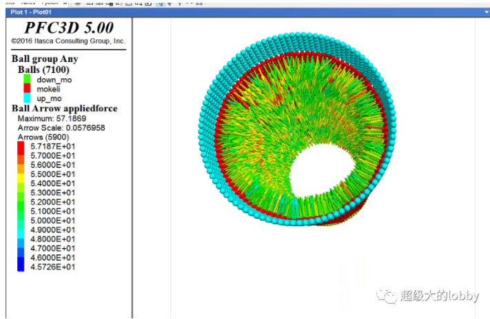
效果如图,这里展示的是施加力的矢量图。
5 加载
这里不多讲了
restore rousifuhistory deleteset mech age 0ball attribute displacement multiply 0set fish callback -1.0 remove @servo_wallshuxiang[strainRate=1e-2]wall attribute zvel [strainRate*wlz] range id 2wall attribute zvel [-strainRate*wlz] range id 1ball attribute zvel [strainRate*wlz] range group down_moball attribute zvel [-strainRate*wlz] range group up_mo[Iz0=wlz]def jiancewlz=wall.pos.z(wp_up)-wall.pos.z(wp_down)-keli_rdmax*10wezz=(wlz-Iz0)/Iz0endset fish callback -1.1 @jiancehistory deletehistory id 10 @stressXXhistory id 11 @stressYYhistory id 12 @stressZZhistory id 1 @wszzhistory id 2 @wezz[stop_me=0]def stop_meif wezz<-20e-2 thenstop_me=1endifend[baocunpinlv=2e-3][time_record=wezz 1][count=0]def savefileif time_record-wezz >= baocunpinlv thenfilename=string.build("jieguo_%1",count)commandsave @filenameendcommandtime_record=wezzcount =1endifendset fish callback -1.0 @savefilesolve fishhalt @stop_mesave result
6 结果分析
先看一下最后的模型图:
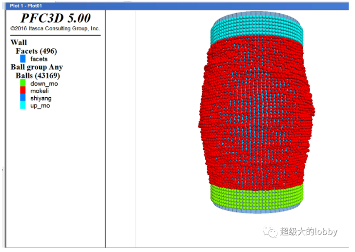
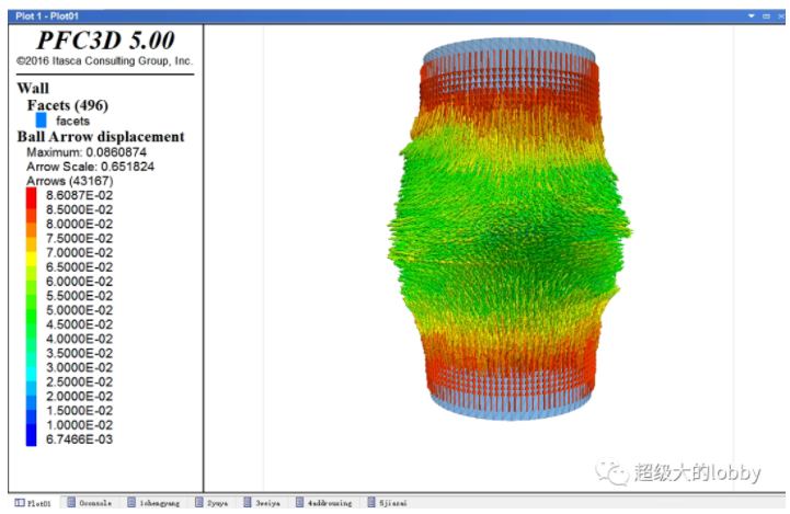
这应该是一个特别理想的一个柔性三轴图了。有特别明显的剪胀现象,从位移矢量中也可以看出来。
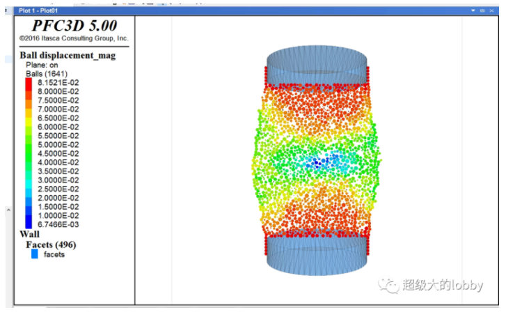
三维的分析肯定是要切片看看的,这种X滑裂面还是比较明显的。
但是和二维对比的话,这里的数目反应在二维上可能只有2000左右的数目。这也是为什么三维的模拟对颗粒的数量要求很高。
这里和二维一样,做一个孔隙率的分析。
应力应变
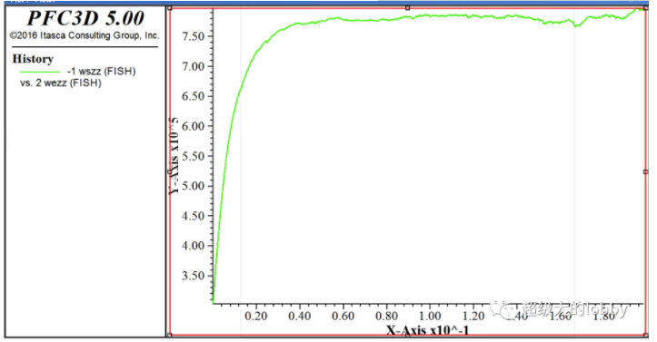
0.4孔隙率:
0.32孔隙率:
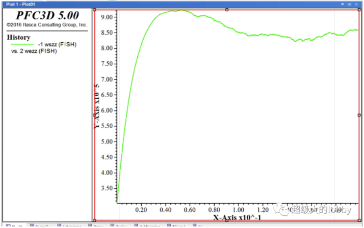
0.25孔隙率:
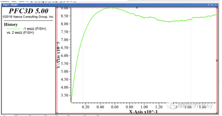
这里可能由于颗粒数的原因有一定的误差,但是更多的原因可能是别的。
那就是最低孔隙率。
最低孔隙率的概念我应该是第一次提,对于每个级配的式样,在合理范围内都应当有一个最低限的孔隙率,超过这个孔隙率将会使得结果变得不再合理。
比如对于等粒径得颗粒,最低得孔隙率就是1-pi/4。低于这个数值我们可以设置,但是这个已经不符合常规得物理常识了。
这部分得理论后面我会单开一篇文章进行讲解。
就本文来说,定性还是没问题得,松砂硬化,密砂软化。
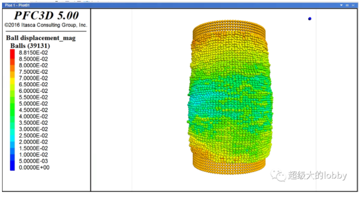
位移图:
0.4孔隙率
0.32孔隙率
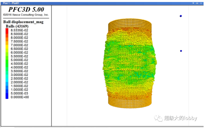
0.25孔隙率
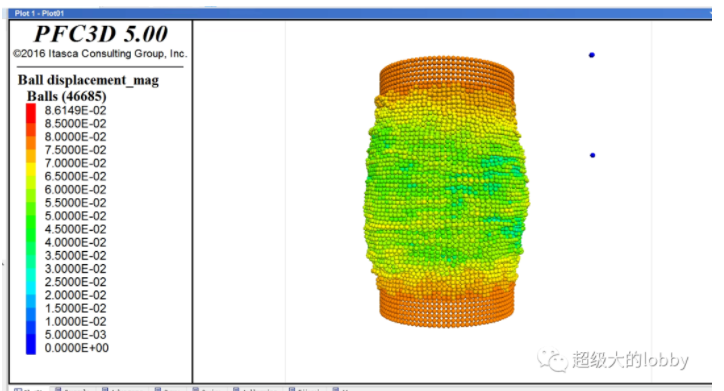
从位移图上看,松砂剪缩,密砂剪胀得现象也是比较明显得。
最后放三个孔隙率对应得动图,关于柔性三轴得更多特性靠各位去探索了。
0.4
.gif?imageView2/1/w/750/h/583 "20220719175357-640 (12).gif")
0.32
.gif?imageView2/1/w/727/h/613 "20220719175441-640 (13).gif")
0.25
.gif?imageView2/0 "20220719175542-640 (14).gif")