ANSYS workbench ECAD导入方法
一般做结构仿真忽略了PCB局部的各向异性,通过在workbench对详细pcb模型仿真,可以得到精确的应力结果,但计算量过大,现在ANSYS 一般采用材料映射的方法对PCB进行材料属性赋值(非ACT插件),可以减小计算量,减小了PCB单一材料赋值对结果的影响。
文章来自ANSYS官网,通过翻译工具,供大家参考与交流~
Many of our customers are reaping the benefits of the trace import functionality in Ansys Mechanical, which accounts for the effects of copper distribution on every layer of a printed circuit board (PCB) — or printed circuit board assembled (PBA) — for your thermal stress analysis, modal, shock and random vibration simulations. Just think — you can capture the accuracy necessary to confidently make engineering decisions in a fraction of the time you are currently spending on lumped parameter models. In this post, I’ll give you a brief overview and explanation of the process.
我们的许多客户正在从Ansys Mechanical的迹线导入功能中获益,该功能可考虑印刷电路板(PCB)或印刷电路板组装(PBA)每一层上的铜分布影响,从而用于热应力分析、模态、冲击和随机振动仿真。试想一下,您可以捕获必要的准确性,从而自信地做出工程决策,而所需时间只是您目前在集总参数模型上花费的一小部分时间。在这篇文章中,我将简要概述和解释该过程。
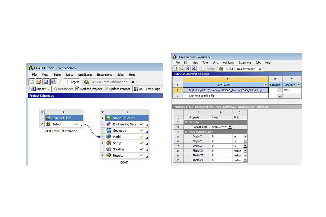
For those new to the idea of trace import, it is critical to highlight that the detailed traces, vias, etc. are not being meshed. Instead, it is the material properties that are being mapped onto the finite element mesh. As shown in Figure 1, this functionality is implemented by dragging and dropping external data to connect the data to the Model cell of any structural simulation. Under the hood, the trace import function performs a “rule of mixtures” calculation on the material properties based upon the fractions of metal and dielectric in each element, and then assigns this set of material properties onto each finite element. Before trace import was added, you would need to first create the PCB geometry, extract the metal fraction for each layer, and then calculate the equivalent lumped material property set. Not only was this a time consuming and tedious process, it provided a significantly less accurate solution
对于那些不熟悉跟踪导入想法的人来说,强调详细的跟踪、过孔等至关重要。未进行网格划分。相反,是材料属性映射到有限元网格上。如图 1 所示,此功能是通过拖放外部数据将数据连接到任何结构仿真的 Model 单元来实现的。在引擎盖下,跟踪导入功能根据每个元素中金属和电介质的分数对材料属性执行“混合规则”计算,然后将这组材料属性分配给每个有限元素。在添加迹线导入之前,您需要首先创建 PCB 几何图形,提取每层的金属部分,然后计算等效的集总材料属性集。这不仅是一个耗时且乏味的过程,而且还提供了精度低得多的解决方案。
Figure 1. Screen shot of the Workbench platform Trace information is connected into a structural analysis and SpaceClaim is used for the PCB layer geometry.
图1.工作台平台的屏幕截图 跟踪信息连接到结构分析中,SpaceClaim用于PCB层几何形状。
Now that we have the trace information without meshing the traces, where does the PCB geometry come from? Ansys SpaceClaim. The SpaceClaim 3-D modeling software filters out all the detailed trace information and imports only the PCB layers into Ansys Mechanical. Ansys Mechanical then meshes the PCB layers and maps the spatially distributed material properties onto them.
现在我们有了迹线信息而不对走线进行网格划分,PCB几何形状从何而来?Ansys SpaceClaim.SpaceClaim 3-D建模软件会过滤掉所有详细的迹线信息,并仅将PCB层导入Ansys Mechanical。然后,Ansys Mechanical对PCB层进行网格划分,并将空间分布的材料属性映射到这些层上。
The most common pitfall of this process is in the first step of importing the geometry into SpaceClaim: setting the Import mode to Layer Topology. The setting is in the ECAD file options of the SpaceClaim Options (available via File→SpaceClaim Options).
此过程最常见的陷阱是将几何图形导入 SpaceClaim 的第一步:将导入模式设置为图层拓扑。该设置位于“空间声明选项”的“ECAD 文件选项”中(可通过“文件→空间声明选项”获得)。
If you choose Layer Geometry, you will import all of the detailed trace information. Notice that in Figure 2A with Layer Topology selected, only the PCB layers are imported, whereas in Figure 2B with Layer Geometry selected, 27,238 bodies representing components, traces, vias, etc. are imported, which is nearly impossible to mesh. This is why we’re using trace import
如果选择图层几何图形,则将导入所有详细的追踪信息。请注意,在选择了层拓扑的图2A中,仅导入PCB层,而在选择层几何形状的图2B中,27,238个实体代表元件,走线,过孔等。是导入的,这几乎不可能网格化。这就是我们使用跟踪导入的原因


Figure 2. (A) Layer Topology selection on ECAD file options filters most details. (B) Layer Geometry selection on ECAD file options imports 27,238 bodies, which is nearly impossible to mesh.
图2.(A) ECAD 文件选项上的层拓扑选择可过滤最详细的信息。(B) ECAD 文件选项上的层几何选择可导入 27,238 个实体,这几乎不可能进行网格划分。
Now that the geometry is imported into SpaceClaim, you will probably want to add components for heat sources or to study their attach integrity in a static or dynamic structural analysis. You can do this in the SpaceClaim environment. It is important to realize that the PCB must remain a multibodied component in Ansys Mechanical and contact elements are used to connect the PCB to the added components. This means in SpacecClaim that all layers of the PCB must be in its own unique component and its topology must be shared.
现在几何图形已导入到 SpaceClaim 中,您可能希望在静态或动态结构分析中添加热源元件或研究其附着完整性。您可以在 SpaceClaim 环境中执行此操作。重要的是要认识到,在Ansys Mechanical中,PCB必须保持为多体组件,并且使用接触元件将PCB连接到添加的组件。这意味着在SpacecClaim中,PCB的所有层都必须在其自己独特的组件中,并且其拓扑必须共享。
Even when importing the ECAD geometry with Layer Topology selected, stray components may be imported — this is included in the tutorial. Notice in Figure 3, under the STP component that the stray parts are imported under Components (STP). You can either uncheck Components (STP) and these hidden parts will not be imported into Ansys Mechanical, or right-click on Components (STP) and choose Move to New Component. Regardless of your choice, the topology of the STP component must be shared as shown in Figure 4A. This creates the multibodied part [integral mesh] of the PCB necessary for the trace import to map the material properties.
即使在选择层拓扑的情况下导入 ECAD 几何图形,也可能导入杂散元件 — 本教程中已包含此项内容。请注意,在图 3 中,在 STP 组件下,杂散部件在组件 (STP) 下导入。您可以取消选中组件(STP),这些隐藏的组件将不会导入到Ansys Mechanical中,也可以右键单击组件(STP)并选择移至新组件。无论您的选择如何,都必须共享 STP 组件的拓扑,如图 4A 所示。这将创建 PCB 的多体部分 [整体网格],这是迹线导入以映射材料属性所必需的。

Figure 3. SpaceClaim screen capture of an imported TGZ file. The PCB layers must be contained in their own component.
图3.导入的 TGZ 文件的 SpaceClaim 屏幕截图。PCB层必须包含在自己的组件中。

Figure 4. (A) The topology of the PCB must be shared to create a multibodied part in ANSYS Mechanical.(B) If there are any other parts or components with the PCB, their topology must not be shared and contact elements in ANSYS Mechanical will be used to connect them together.
图4.(A) 必须共享PCB的拓扑结构,才能在ANSYS Mechanical中创建多体器件。(B)如果PCB存在任何其他零件或组件,则不得共享其拓扑结构,并且将使用ANSYS机械中的接触元件将它们连接在一起。
Now that the PCB component has a shared topology, the trick to adding components in SpaceClaim is to first ensure the No Merge option is selected when extruding parts, and then use the ruler to locate the components off the edges of the PCB, as shown in Figure 5. Once you add components as described here, or if you opt to move Components (STP) to new components, you need to go back to Figure 4B and make sure that the topology for all these components and parts is NOT shared. Contact elements will be used to connect the PCB to these additional parts and/or components.
现在PCB元件具有共享拓扑,在SpaceClaim中添加元件的诀窍是首先确保在拉伸元件时选择“不合并”选项,然后使用标尺将元件定位在PCB边缘之外,如图5所示。按照此处所述添加组件后,或者选择将组件 (STP) 移动到新组件后,您需要返回到图 4B,并确保所有这些组件和部件的拓扑未共享。接触元件将用于将PCB连接到这些附加零件和/或组件。

Figure 5. Tricks to adding components to PCB. Select No Merge when creating parts and use the ruler to locate the parts (for example, PCB edges).
图5.将组件添加到PCB的技巧。创建零件时选择“不合并”,然后使用标尺定位零件(例如,PCB 边缘)。
After the geometry is defined in SpaceClaim and imported into Ansys Mechanical, then the trace information is imported onto the PCB bodies. If parts in addition to the PCB have been imported, then make sure to select only the PCB bodies when scoping the imported trace, as highlighted in Figure 6. Note that multiple PCBs and their trace files can be incorporated into the same analysis; each will have its own unique external data modifier, as shown in File1 in Figures 1 and 6. Remember to assign each layer of the PCB as the dielectric (typically FR-4) under the Geometry branch of the outline tree and define the metal material under the Imported Trace as shown in Figure 6. Once the PCB is meshed and the trace information imported, the user can view the metal fraction, also shown in Figure 6.
在SpaceClaim中定义几何结构并将其导入Ansys Mechanical后,迹线信息将导入PCB主体。如果已导入除PCB以外的零件,请确保在确定导入的走线范围时仅选择PCB主体,如图6所示。请注意,多个PCB及其跟踪文件可以合并到同一分析中;每个修饰符都有自己唯一的外部数据修饰符,如图 1 和图 6 中的 File1 所示。请记住,将PCB的每一层指定为轮廓树的几何分支下的电介质(通常为FR-4),并在导入的走线下定义金属材料,如图6所示。一旦PCB网格化并导入了走线信息,用户就可以查看金属部分,如图6所示。
The ECAD file formats Ansys Mechanical and SpaceClaim are capable of importing include: Cadence BRD/MCM/SIP, ODB++ [TGZ], Ansoft ANF, Icepak BOOL+INFO or COND+INFO. The example here imports an ODB++ [TGZ] file. As shown in Figure 1, you can apply a rigid body transformation if the global CS of the simulation and the ECAD file are different.
Ansys Mechanical和SpaceClaim能够导入的ECAD文件格式包括:Cadence BRD/MCM/SIP、ODB++ [TGZ]、Ansoft ANF、Icepak BOOL+INFO或COND+INFO。此处的示例导入 ODB++ [TGZ] 文件。 如图 1 所示,如果仿真的全局 CS 和 ECAD 文件不同,则可以应用刚体变换。
It might be useful to point out that the trace import function is the same function Ansys Icepak has had for several releases. Icepak is an Ansys module that provides best-in-class electronic cooling simulation using the Ansys Fluent solvers. You can also perform thermal analysis in Ansys Mechanical when the heat transfer is dominated by conduction. Temperature distributions from either Icepak or Ansys Mechanical can easily be mapped into Ansys Mechanical for thermal-stress analyses.
需要指出的是,跟踪导入功能与Ansys Icepak在多个版本中具有的功能相同。Icepak是一款Ansys模块,使用Ansys Fluent求解器提供一流的电子冷却仿真。当传热以传导为主时,您还可以在Ansys Mechanical中执行热分析。来自Icepak或Ansys Mechanical的温度分布可以很容易地映射到Ansys Mechanical中进行热应力分析。

A cracked solder joint results from the glass transition effect of an acrylic conformal coating that bridges the component body and board.
焊点裂纹是由连接元件主体和电路板的丙烯酸保形涂层的玻璃化转变效应引起的。
If you want to learn more about trace import functionality, we have lots of additional resources for you at Ansys Structures.
如果您想了解有关迹线导入功能的更多信息,Ansys Structures为您提供了大量其他资源。
登录后免费查看全文
求解技术电子芯片消费电子自动驾驶汽车新能源通用半导体流-固&热耦合静力学振动疲劳结构基础热设计Mechanical APDLSpaceClaimIcepakWorkbenchMechanicalFluent
著作权归作者所有,欢迎分享,未经许可,不得转载
首次发布时间:2023-06-15
最近编辑:11月前

硕士
|
仿真工程师
thermal design


课程培训服务行家
课程
培训
服务
行家